4.2.2 XSCF Cable Connections via a Crossbar Box
4.2.2 XSCF Cable Connections via a Crossbar Box
In the case of connections via a crossbar box, the expansion rack will be shipped with the SPARC M12-2S and crossbar box mounted in it. The XSCF cable for connecting XSCF units together will also be shipped connected to them. The connection work is not necessary for a system of up to the 8BB configuration since it has only one expansion rack.
Since two expansion racks are used for the configuration of 9BB or more, the XSCF cable interconnecting the racks need to be connected. This section describes how to connect the cables interconnecting the racks.
Cables that pass between racks are secured to expansion rack 2. Wire cables from expansion rack 2 to expansion rack 1 and connect them to the respective ports.
For each configuration, "Appendix B Cable Connection Information on Building Block Configurations" provides a cable routing diagram of connections (Figure 4-5) and a cable list.
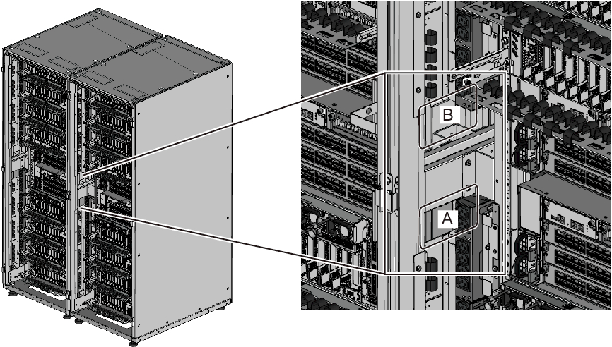
- Pass the XSCF BB control cables stored in expansion rack 2 through the upper side of the connecting part of the racks. (B in Figure 4-4)
When wiring the cables, use the supplied hook-and-loop fastener strips to bundle them.
|
Figure 4-4 Locations for Passing Cables Between the Racks
|
|
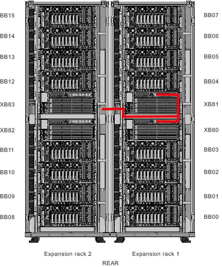
- Connect the XSCF BB control cables.
Each cable has an attached label showing the connection destination port.
Connect the cable to the port corresponding to the label. - Check the connection of the XSCF DUAL control cable.
Confirm that the cable is connected between the XSCF DUAL control port of XBBOX#80 and the XSCF DUAL control port of XBBOX#81.
|
Figure 4-5 Cable Wiring Diagram
|
|
< Previous Page | Next Page >