2.4.5 Bottom View of Expansion Rack
2.4.5 Bottom View of Expansion Rack
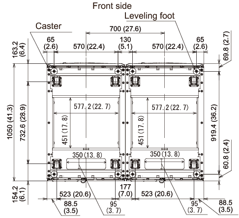
Figure 2-9 shows the locations of openings for taking out/in cables, the leveling feet, and the casters on the bottom of the expansion rack. This figure shows the perspective view of the bottom base of the expansion rack when viewed from the top.
Note that the values shown are the design values of the expansion rack. When the feet are secured to the floor, determine the positions by considering the dimensional tolerance of the expansion rack, ±2 mm (±0.1 in.).
|
Figure 2-9 Bottom View of Expansion Rack, Unit: mm (in.)
|
|
< Previous Page | Next Page >