4.4.2 When the Rack Width is 600 mm
4.4.2 When the Rack Width is 600 mm
In a rack with a width of 600 mm (23.6 in.), there is not enough space for storing crossbar cables at the sides of the rack. You need to distribute cables appropriately and bundle them together.
This section describes the recommended method of storing the cables.
This section describes the recommended method of storing the cables.
- Storing crossbar cables (optical) when connected
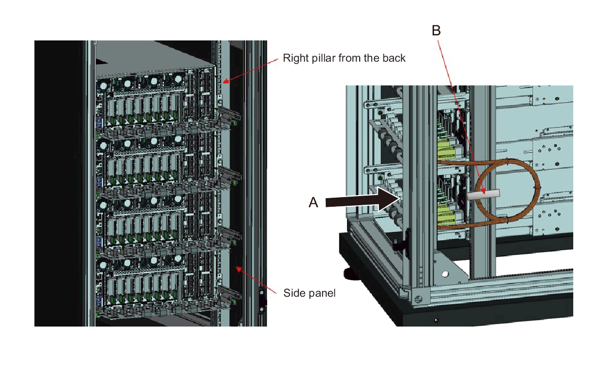
- Store the crossbar cables (optical) in an empty space at the right side as viewed from the rear of the rack.a. Insert them in the gap between the pillar at the rear right side of the device and the side panel of the rack. (A in Figure 4-26)b. Fasten them with a hook-and-loop fastener strip to the pillar at the rear right side of the device. (B in Figure 4-26)c. Repeat this work for all connected crossbar cables (optical).
| Note - When the work of storing the bundled cables is difficult, perform work from the rear of the rack. Figure 4-26 illustrates how the work is seen from the side. However, since the rack has a side panel, working from the side is not possible. |
|
Figure 4-26 Cable Storing Method (When the Rack Width is 600 mm)
|
|
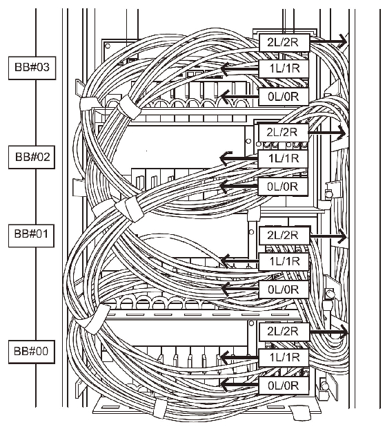
- Connected crossbar cables (electrical) in the 4BB configuration
For the 4BB configuration, place the crossbar cables (electrical) connected to the 2L/2R ports of XBU#0/#1 together at the right side as viewed from the rear of the rack. Place cables other than the crossbar cables (electrical) together at the left side as viewed from the rear of the rack.
- Place the crossbar cables (electrical) connected to the 0L/0R and 1L/1R ports of each XBU together at the left side as viewed from the rear of the rack.
- Secure the crossbar cables (electrical) bundled together on the left side to the cable support with hook-and-loop fastener strips.
- Place the crossbar cables (electrical) connected to the 2L/2R ports of each XBU together at the right side as viewed from the rear of the rack.
- If a cable holder is supplied for the rack used, secure the crossbar cables (electrical) bundled together on the right side to the cable holder in the rack.
|
Figure 4-27 Example of cable storage (4BB configuration)
|
|
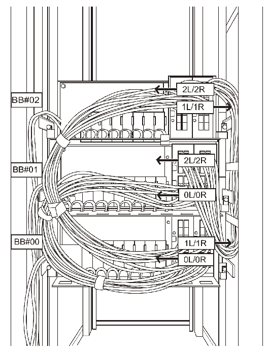
- Connected crossbar cables (electrical) in the 3BB configuration
For the 3BB configuration, place the crossbar cables (electrical) connected to the 1L/1R ports of XBU#0/#1 together at the right side as viewed from the rear of the rack. Place cables other than the crossbar cables (electrical) together at the left side as viewed from the rear of the rack.
- Place the crossbar cables (electrical) connected to the 0L/0R and 2L/2R ports of each XBU together at the left side as viewed from the rear of the rack.
- Secure the crossbar cables (electrical) bundled together on the left side to the cable support with hook-and-loop fastener strips.
- Place the crossbar cables (electrical) connected to the 1L/1R ports of each XBU together at the right side as viewed from the rear of the rack.
- If a cable holder is supplied for the rack used, secure the crossbar cables (electrical) bundled together on the right side to the cable holder in the rack.
|
Figure 4-28 Example of cable storage (3BB configuration)
|
|
< Previous Page | Next Page >