1.1.3 Connections via a Crossbar Box (With an Expansion Rack)
1.1.3 Connections via a Crossbar Box (With an Expansion Rack)
The connections via a crossbar box are in a configuration connecting units of the SPARC M12-2S to each other through crossbar cables and XSCF cables (XSCF BB control cables and XSCF DUAL control cables). This can be expanded to up to the 16BB configuration.
The crossbar box is mounted in the expansion rack. In the expansion rack, a dedicated receptacle box for supplying power, crossbar cables, and XSCF cables are mounted in addition to the crossbar box.
The crossbar box is mounted in the expansion rack. In the expansion rack, a dedicated receptacle box for supplying power, crossbar cables, and XSCF cables are mounted in addition to the crossbar box.
This section describes a building block configuration using a crossbar box. Also described is the flow from installation of the optional PCI expansion unit, which will be connected to the SPARC M12-2S, to the initial setting of the system.
The initial system settings are the settings implemented before system startup, and they include the XSCF setup, CPU Activation setting, and physical partition configuration. Skip the steps for the PCI expansion unit if it is not to be installed.
The initial system settings are the settings implemented before system startup, and they include the XSCF setup, CPU Activation setting, and physical partition configuration. Skip the steps for the PCI expansion unit if it is not to be installed.
| Note - The crossbar cables used for connections via a crossbar box are crossbar cables (optical). |
| Note - Generally, there is no problem when the physical partition number for a physical partition being configured matches any of the existing SPARC M12-2S IDs (BB-IDs) in the system. However, if you anticipate that the system may be reduced after operation starts, you need to consider the appropriate physical partition number for that case when determining the physical partition number. This is because any physical partition with a physical partition number that is the same as the BB-ID of the SPARC M12-2S to be removed must be stopped at the time of reduction. Before configuring a physical partition, be sure to see "Chapter 4 Configuring a Physical Partition" in the Fujitsu SPARC M12 and Fujitsu M10/SPARC M10 Domain Configuration Guide and check the recommended method of configuring a physical partition. |
|
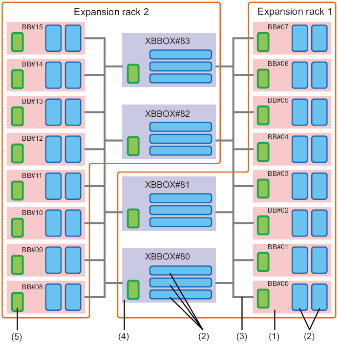
Figure 1-2 Case of Connections via a Crossbar Box
|
|
| Number in Figure | Description |
| 1 | SPARC M12-2S |
| 2 | Crossbar unit |
| 3 | Crossbar cable, XSCF BB control cable, XSCF DUAL control cable |
| 4 | Crossbar box |
| 5 | XSCF unit |
The number shown after BB# or XBOX# is the ID (BB-I). BB-IDs are set in order from 00 for the SPARC M12-2S and from 80 for a crossbar box.
By clicking a reference in " " to display a section, you can see the details of the respective step. Italic font is used to indicate the name of a reference manual other than this manual.
| Step (Work Time (*1)) | Work Description | Reference | |
|---|---|---|---|
| Installation work (approx. 59 minutes/280 minutes (*2)) | |||
| 1 | Check the latest information available in the Fujitsu SPARC M12 Product Notes. | Fujitsu SPARC M12 Product Notes | Required |
| 2 | Before installing the system, check the safety precautions, system specifications, and necessary conditions for installation. | "Chapter 2 Planning and Preparing for System Installation" | Required |
| 3 | Prepare the necessary tools/information for installation. | "3.1 Preparing the Necessary Tools/Information for Installation" | Required |
| 4 | Confirm the delivered components. | "3.2.1 Confirming the Delivered Components of the SPARC M12-2S" | Required |
| "3.2.3 Confirming the Delivered Components of the Expansion Rack" | Required | ||
| "3.2.2 Confirming the Delivered Components of the PCI Expansion Unit" | Optional | ||
| 5 | Install the rack. | See the manual for each rack. "3.3.2 Fastening the Rack" |
Required |
| 6 | Connect expansion rack 1 and expansion rack 2. | "3.3.3 Coupling Racks" | Required (*3) |
| 7 | Mount the PCI expansion unit in the rack. | "3.4.2 Mounting the PCI Expansion Unit in a Rack" | Optional |
| 8 | If there are optional components, mount them in the SPARC M12-2S or PCI expansion unit. | "3.5.1 Mounting Optional Components in the SPARC M12-2S" | Optional (*4) |
| "3.5.2 Mounting Optional Components in the PCI Expansion Unit" | Optional (*4) | ||
| 9 | Set up the IDs necessary for identifying each SPARC M12-2S chassis and crossbar box chassis. | "4.1 Setting the ID (BB-ID) Identifying the SPARC M12-2S" | Required |
| 10 | Connect the XSCF cable to the crossbar box mounted in expansion rack 1. | "4.2.2 XSCF Cable Connections via a Crossbar Box" | Required (*3) |
| 11 | Connect the crossbar cable to the chassis. | "4.3.2 Crossbar Cable Connections via a Crossbar Box" | Required |
| 12 | Connect serial cables and power cords to crossbar boxes. | "5.3 Connecting Cables to the Crossbar Box" | Required (*5) |
| 13 | Connect the GbE LAN cable and power cord to the SPARC M12-2S. | "5.1 Connecting Cables to the SPARC M12-2S" | Required (*5) |
| 14 | If there is a PCI expansion unit, connect the link cables and management cable to the PCI expansion unit. Attach the core to the power cord, and connect the power cord to the power supply unit. |
"5.2 Connecting Cables to the PCI Expansion Unit" | Optional (*6) |
| Initial diagnosis (approx. 117 minutes/151 minutes) | |||
| 15 | Connect the system management terminal to the crossbar box that works as the master XSCF. | "6.1 Connecting the System Management Terminal" | Required |
| 16 | Confirm that an identification ID (BB-ID) is set to each SPARC M12-2S chassis and crossbar box chassis. | "6.2.1 Checking the BB-ID Settings" | Required |
| 17 | Turn on the input power. | "6.2.2 Turning On the Input Power and Starting the XSCF" | Required |
| 18 | Log in to the master XSCF of the SPARC M12-2S. Confirm the XCP firmware version, and set the altitude and time. | "6.3 Logging In to the XSCF" "6.4 Confirming the XCP Firmware Version" "6.5 Checking the Altitude Setting" "6.6 Setting the Time" |
Required |
| 19 | Perform the initial diagnosis test on the hardware. | "6.7 Performing a Diagnosis Test" | Required |
| 20 | Check the status of mounted components. | "6.8 Checking the Component Status" | Required |
| Initial system settings (approx. 130 minutes/200 minutes) | |||
| 21 | Set the password policy. | "7.1 Setting the Password Policy" | Required |
| 22 | Set a user account and password. | "7.2 Setting a User Account and Password" | Required |
| 23 | Configure the telnet or SSH service. | "7.3 Configuring the Telnet/SSH Service" | Required |
| 24 | Configure the HTTPS service. | "7.4 Configuring the HTTPS Service" | Required |
| 25 | Configure the XSCF network. | "7.5 Configuring the XSCF Network" | Required |
| 26 | When duplicating memory, configure memory mirroring. | "7.6 Configuring Memory Mirroring" | Optional |
| 27 | Create a PPAR configuration list (PCL). | "7.7 Creating a PPAR Configuration List" | Required |
| 28 | Assign the building block (physical system board (PSB)) to the physical partition. | "7.8 Assigning/Releasing a Physical System Board (PSB) for a Physical Partition (PPAR)" | Required |
| 29 | Clear the difference between the system time and physical partition (PPAR) time. | "7.9 Synchronizing the Physical Partition (PPAR) Time and XSCF Time" | Required |
| 30 | Add a CPU Activation key to the system. | "7.10 Registering a CPU Activation Key" | Required (*7) |
| 31 | Assign CPU resources to the physical partition. | "7.11 Assigning CPU Core Resources" | Required |
| 32 | Confirm the start/stop of the physical partition and the connection of the console. | "7.12.1 Checking the Start and Stop of a Physical Partition (PPAR)" | Required |
| 33 | Either use the preinstalled Oracle Solaris as is or reinstall it. (Note) | "7.13 Installing Oracle Solaris" | Required |
| 34 | Save XSCF setting information and logical domain configuration information. | "7.14 Saving Configuration Information" | Required (*8) |
| *1 Average work time for the 8BB configuration/16BB configuration. The work time is shown in the order of 8BB configuration and 16BB configuration. *2 The time required for mounting optional components and installing the PCI expansion unit is not included. *3 Necessary only when expansion rack 2 is used. *4 If the optional components and the chassis are ordered together, the components are mounted in the chassis before shipment. If the optional components and the PCI expansion unit are ordered together, the components are mounted in the PCI expansion unit before shipment. *5 The power cord between each chassis and receptacle box (PDU) is generally connected before shipment. *6 The link card is mounted in the SPARC M12-2S before shipment. *7 One CD-ROM disk containing a CPU Activation certificate is provided with the system. Or, the CPU Activation key has been registered to the system before shipment. *8 If you have started Oracle Solaris and changed the configuration of a logical domain, save the logical domain configuration information. |
|||
| Note - Oracle Solaris has been preinstalled in the SPARC M12-2S. According to the purpose, either use the preinstalled Oracle Solaris as is or reinstall it. To reinstall Oracle Solaris, install the latest Oracle VM Server for SPARC. For the latest information on the supported Oracle Solaris versions and SRU, see the Fujitsu SPARC M12 Product Notes. |
< Previous Page | Next Page >