4.2.1 XSCF Cable Connection for Direct Connections Between Chassis
4.2.1 XSCF Cable Connection for Direct Connections Between Chassis
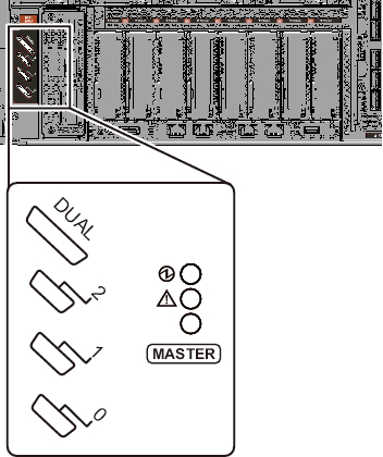
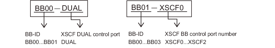
Each cable has an attached label showing the connection destination port. Connect the cable to the port corresponding to the label. All ports for the cable connections are on the rear of the chassis. For port locations and examples of the appearance of the label, see Figure 4-2 and Figure 4-3.
|
Figure 4-2 XSCF Port Locations (SPARC M12-2S Rear Panel Side)
|
|
|
Figure 4-3 Examples of the Appearance of an XSCF Cable Label
|
|
For each configuration, "Appendix B Cable Connection Information on Building Block Configurations" provides a cable routing diagram of connections and a cable list.
- Connect the XSCF DUAL control cable between the XSCF of BB#00 and the XSCF of BB#01.a. Connect the XSCF DUAL cable from the XSCF DUAL control port of BB#00 to the XSCF DUAL control port of BB#01.
The XSCF DUAL control ports are marked DUAL. - For the 2BB or greater configuration, connect an XSCF BB control cable between the XSCF of BB#00 and the XSCF of BB#01.a. Connect the cable from port 0 of BB#00 to port 0 of BB#01.
The XSCF BB control ports are marked 0, 1, and 2 from bottom to top. - For the 3BB or greater configuration, connect XSCF BB control cables to XSCF ports of BB#02, in addition to the connection of step 2.a. Connect the cable from port 1 of BB#00 to port 0 of BB#02.b. Connect the cable from port 1 of BB#01 to port 1 of BB#02.
- For the 4BB configuration, connect XSCF BB control cables to XSCF ports of BB#03, in addition to the connections of steps 2 and 3.a. Connect the cable from port 2 of BB#00 to port 0 of BB#03.b. Connect the cable from port 2 of BB#01 to port 1 of BB#03.
- Store the XSCF DUAL control cable and XSCF BB control cables, connected as described in steps 1 to 4, in an empty space at the right side as viewed from the rear of the rack.
< Previous Page | Next Page >