3.3.3 Coupling Racks
3.3.3 Coupling Racks
When there is expansion rack 2, couple the racks together. When coupling the racks, couple rack 2 to rack 1, which has already been installed.
|

|

In this section, the procedure to couple expansion rack 2 to the right side of expansion rack 1 is described.
- Confirm that all the coupling kit components supplied with expansion rack 2 are ready for use.
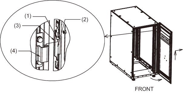
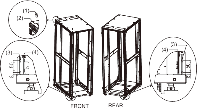
- Remove the front doors of expansion rack 1 and expansion rack 2.a. Open each door by about 90 degrees.b. Lift the door to take out the hinge (pin) on the rack main unit, and remove the door by sliding the door horizontally.
|
|
Figure 3-17 Removing the Front Door
|
|
| Number in Figure | Description |
|---|---|
| 1 | Hinge on door |
| 2 | Part with notch for hinge |
| 3 | Bending restricted by opening angle |
| 4 | Hinge on main unit |
- Remove the rear doors of expansion rack 1 and expansion rack 2.a. Open the door by about 90 degrees.b. Lift the door to take out the hinge (pin) on the rack main unit, and remove the door by sliding the door horizontally.
- Remove the fastening screws from the top cover for expansion rack 1, and remove the side panel.a. Using an Allen wrench, remove the two M12 screws fastening the top cover at the front and rear on the right side, the side to be coupled. The removed screws will not be used.b. Remove the 10 screws fastening the side panel, and remove the side panel.
| Note - Always pay attention to your safety when working in high places, such as on the top cover. Also, avoid putting your foot or weight on the rack, as this is very dangerous. |
| Note - Be careful when removing the side plate because it weighs about 13 kg. |
|
Figure 3-18 Removing the Side Plate
|
|
| Number in Figure | Description |
|---|---|
| 1 | M12 screw |
| 2 | Top cover |
| 3 | Side panel |
| 4 | Screw |
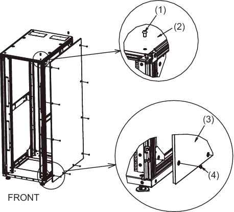
- Attach M6 core spring nuts at the front and rear of expansion rack 1.a. Attach two pieces of M6 core spring nuts to the lower portion of the vertical pillar on the coupling side of the rack front (right side as seen from the front).b. Attach two pieces of M6 core spring nuts to the lower portion of the vertical pillar on the coupling side of the rack rear (left side as seen from the rear).
|
Figure 3-19 Attaching the Core Spring Nuts
|
|
| Number in Figure | Description |
|---|---|
| 1 | M6 core spring nut |
| 2 | Vertical pillar |
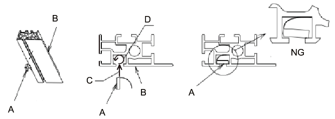
- Procedure for attaching core spring nuts
See Figure 3-20 for this work.a. After inserting the core spring nut A in the groove of vertical pillar B in the direction of C, rotate in the direction of D. This work can be done more easily by using the tip of a pen or thin flathead screwdriver.b. Confirm that the core spring nut is not tilted in the groove of the aluminum frame.
| Note - Check whether the screw section of the core spring nuts can be seen from outside of the groove. |
|
Figure 3-20 Attaching the Core Spring Nuts
|
|
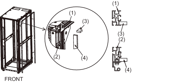
- Affix the coupling seals.a. Affix vertical coupling seal 1 and vertical coupling seal 2 to the vertical pillars at the front and rear on the right side of expansion rack 1. Either one may be affixed in the higher position.
See (4) of Figure 3-21 for the position of affixing.b. Affix the horizontal coupling seal to the horizontal pillar at the upper right of expansion rack 1.
See (3) of Figure 3-21 for the position of affixing.
|
Figure 3-21 Affixing the Coupling Seals
|
|
| Number in Figure | Description |
|---|---|
| 1 | Horizontal pillar |
| 2 | Vertical pillar |
| 3 | Horizontal coupling seal |
| 4 | Vertical coupling seal |
- After removing the fastening screws from the top cover of expansion rack 2, attach M6 core spring nuts at the front and rear of the rack.a. Using a hexagon wrench, remove the two M12 screws fastening the top cover at the front and rear on the left side, the side to be coupled.
| Note - Always pay attention to your safety when working in high places, such as on the top cover. Also, avoid putting your foot or weight on the rack, as this is very dangerous. |
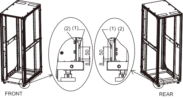
- b. Attach two M6 core spring nuts to the lower part of the vertical pillar on the coupling side at the front of the rack (left side as seen from the front).c. Attach two M6 core spring nuts at the lower part of the vertical pillar on the coupling side at the rear of the rack (right side as seen from the rear).
|
Figure 3-22 Attaching the Core Spring Nuts (Expansion Rack 2 Side)
|
|
| Number in Figure | Description |
|---|---|
| 1 | M12 screw |
| 2 | Top cover |
| 3 | M6 core spring nut |
| 4 | Vertical pillar |
- Align the heights of expansion rack 2 and expansion rack 1.a. Place expansion rack 2 to the side of expansion rack 1.b. Adjust the leveling feet of expansion rack 2 to align the heights of the two racks.
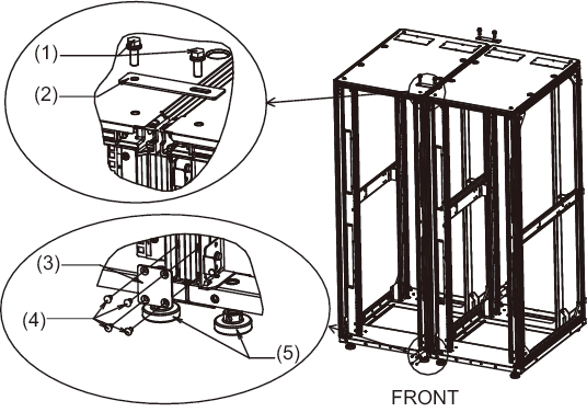
- Attach the upper and lower coupling brackets.a. Align the upper coupling bracket on the top covers of expansion rack 1 and rack 2, and temporarily attach it with M12 hexagon bolts.
| Note - Confirm that the heights of expansion racks 1 and 2 are aligned. If not aligned, adjust with the leveling feet. |
| Note - Always pay attention to your safety when working in high places, such as on the top cover. Also, avoid putting your foot or weight on the rack, as this is very dangerous. |
| Note - If a coupling seal protrudes or is recessed when you align expansion racks 1 and 2, adjust it by pulling or pushing it with your fingers. |
| Note - Before attaching the coupling brackets, check the packing condition of the cables stored in the expansion rack 2. It may be impossible to pull out the cables that pass across the racks after the coupling brackets are fixed. As needed, unpack the cables that pass across the racks, and pass them to expansion rack 1 (see 4.2.2 and 4.3.2) so that they can be taken out. For unpacking and the location of the packed cables, see "4.3.2 Crossbar Cable Connections via a Crossbar Box." |
- b. In steps 5 and 7, use the M6 core spring nuts attached to the pillars at the front and rear of the rack, to fasten the lower coupling bracket with M6 countersunk screws.c. Finally tighten the M12 hexagon bolts to secure the temporarily attached upper coupling bracket.
|
Figure 3-23 Attaching the Coupling Brackets
|
|
| Number in Figure | Description |
|---|---|
| 1 | M12 hexagon bolts |
| 2 | Upper coupling bracket |
| 3 | Lower coupling bracket |
| 4 | M6 countersunk screw |
| 5 | Leveling foot |
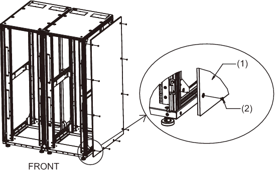
- Attach the side panel to expansion rack 2.
Attach the ten screws removed from the side panel of expansion rack 1 to the side panel of expansion rack 1.
| Note - Be careful when attaching the side plate because it weighs about 13 kg. |
|
Figure 3-24 Attaching the Side Panel
|
|
| Number in Figure | Description |
|---|---|
| 1 | Side panel |
| 2 | Screw |
- Attach the front and rear doors of expansion rack 1 and expansion rack 2.
The work is completed after the front and rear doors are attached.
< Previous Page | Next Page >