3.3.1 Connecting the Power Cords to the Power Distribution Units of an Expansion Rack
3.3.1 Connecting the Power Cords to the Power Distribution Units of an Expansion Rack
This section describes the procedure for connecting the power cords to the power distribution units (PDUs) of an expansion rack (referred to below as the rack).
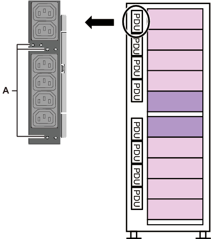
- Turn off the circuit breaker switches (CB switches) on the PDUs.
Open the rear door of the rack, and pull out all the CB switches on the PDUs.
When pulled out, a CB switch is turned off. When pushed in, the switch is turned on.
- A PDU has six CB switches (A in Figure 3-3).
In each expansion rack, the number of CB switches on a PDU is as follows.- Single-phase power feed:
8 PDUs mounted per rack, so 6 CB switches x 8 PDUs = total of 48 CB switches- Three-phase power feed:
6 PDUs mounted per rack, so 6 CB switches x 6 PDUs = total of 36 CB switches
(Though the number of mounted PDUs is different for three-phase feed, the CB switch locations on the PDUs are the same.)
Keep the CB switches turned off until you turn them on in "6.2.2 Turning On the Input Power and Starting the XSCF."
|
Figure 3-3 Locations of the CB Switches on the PDUs
|
|
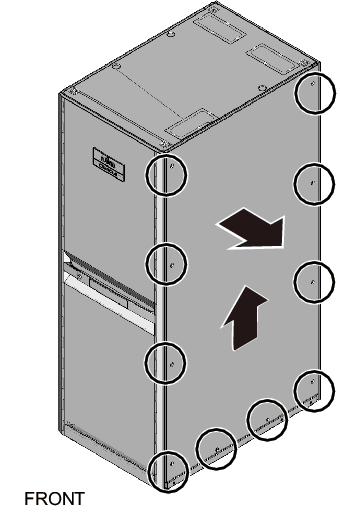
- Remove the side plate on the right side as viewed from the front of the rack.a. Remove the 10 screws securing the side plate.b. Remove the side plate by lifting it up.
The side plate is secured by the bracket on the top of the rack.
The side plate is released by lifting it up about 20 to 30 mm.
| Note - Be careful when removing the side plate because it weighs about 13 kg. |
| Remarks - Expansion rack 2 does not have the side plate. |
|
Figure 3-4 Removing the Side Plate
|
|
- Connect the power cords.
The wiring of the power cords may run from above the rack or below the rack. Perform this work by following the corresponding procedure.
Wiring the power cords from above the rack (ceiling side)
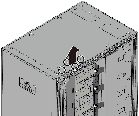
- a. Remove the four screws securing the top cover of the rack.b. Remove the top cover by lifting it up.
| Note - Be careful because work on the top cover section is done high off the ground. Never do anything dangerous such as putting your foot on the rack, which would be very dangerous. |
|
Figure 3-5 Removing the Top Cover
|
|
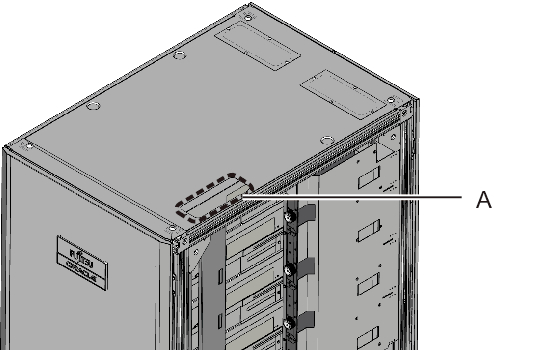
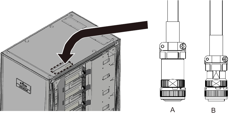
- c. Fit the protection bushing (A in Figure 3-6) in the top opening of the rack.
|
Figure 3-6 Fitting in the Protection Bushing
|
|
- d. Insert the PDU connection side of the power cords through the top opening of the rack.
A in Figure 3-7 represents the power cord for single-phase power feed and three-phase delta power feed.
B in Figure 3-7 represents the power cord for three-phase star power feed.
|
Figure 3-7 Inserting Power Cords
|
|
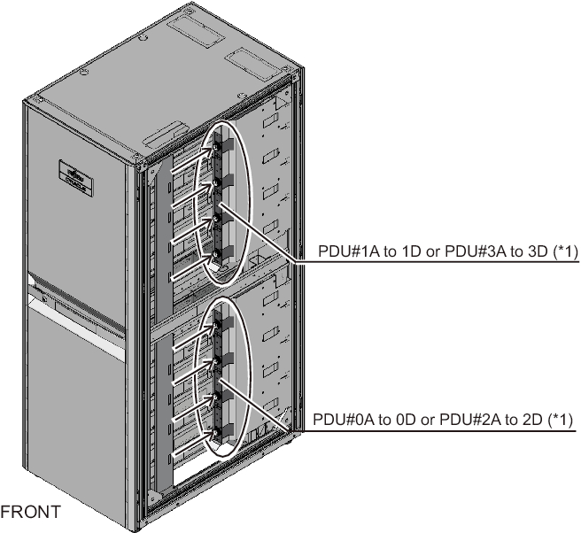
- e. Connect the power cords to the PDUs.
Each cable has an attached label showing the connection destination. Each PDU also has an indicator. So, match it with the right cable to connect the cable. For the PDU mounting locations, see Figure 3-8.
|
Figure 3-8 Connecting Power Cords
|

|
| *1 PDU#0 and PDU#1 are for expansion rack 1. PDU#2 and PDU#3 are for expansion rack 2. |
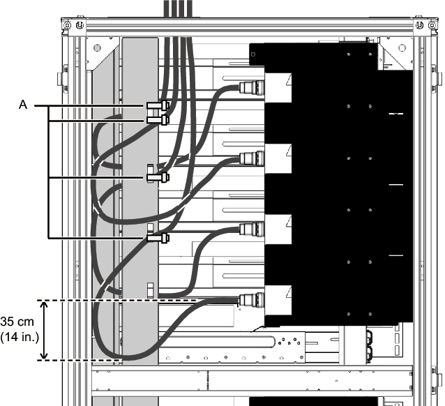
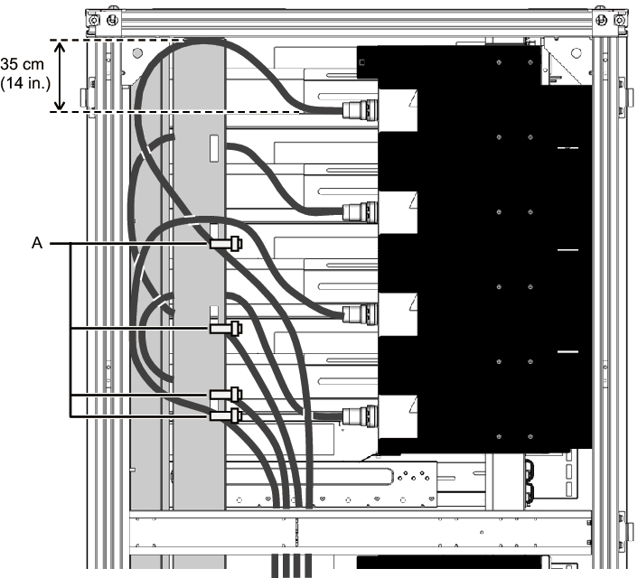
- f. Secure all the power cords to the column, with the supplied binding bands (A in Figure 3-9).
When securing them, allow an extra length of about 35 cm (14 in.) in each power cord.
| Remarks - Figure 3-9 shows single-phase power feed. The required lengths are the same as for three-phase power feed. |
|
Figure 3-9 Securing Power Cords
|
|
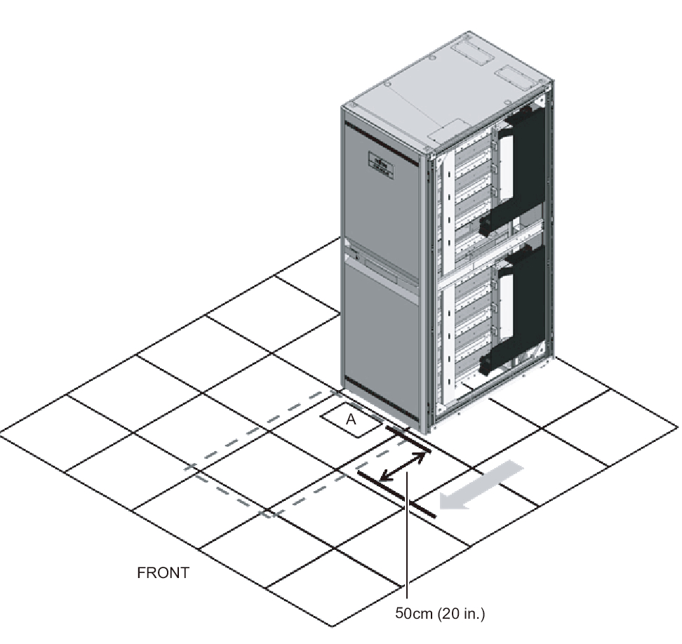
Wiring the power cords from below the rack (floor side)
- a. Move the rack forward 50 cm (20 in.) from the power cord opening (A in Figure 3-10).
|
Figure 3-10 Moving the Rack
|
|
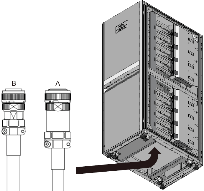
- b. Draw in the PDU connection side of the power cords into the rack through the power cord opening.A in Figure 3-11 represents the power cord for single-phase power feed and three-phase delta power feed.B in Figure 3-11 represents the power cord for three-phase star power feed.
|
Figure 3-11 Drawing in Power Cords
|
|
- c. Connect the power cords to the PDUs.
Each cable has an attached label showing the connection destination. Each PDU also has an indicator. So, match it with the right cable to connect the cable. For the PDU mounting locations, see Figure 3-12.
|
Figure 3-12 Connecting Power Cords
|
|
| *1 PDU#0 and PDU#1 are for expansion rack 1. PDU#2 and PDU#3 are for expansion rack 2. |
- d. Secure all the power cords to the column, with the supplied binding bands (A in Figure 3-13).
When securing them, allow an extra length of about 35 cm (14 in.) in each power cord.
|
Figure 3-13 Securing Power Cords
|
|
| Remarks - Figure 3-13 shows single-phase power feed. The required lengths are the same as for three-phase power feed. |
- Attach the side plate that was removed in step 2.
Attach the plate by reversing the removal procedure of step 2. Move the rack as appropriate into position for attaching the side plate. - Move the rack to the installation location.
< Previous Page | Next Page >