
7.4.1 Active Maintenance
7.4.1 Active Maintenance
This section describes the flows of the active replacement, active addition, and active removal of the link card.
References to detailed descriptions are written in the work procedure tables. See any of them as required.
References to detailed descriptions are written in the work procedure tables. See any of them as required.
Precautions for Active Maintenance of the Link Card
- If the link card is mounted on the SPARC M12-1/M10-1, active maintenance cannot be performed. Perform maintenance with the system stopped.
- If the SPARC M12-2/M12-2S or SPARC M10-4/M10-4S is in a single-unit configuration and the setting for the direct I/O function is enabled, active maintenance of the link card cannot be performed. Perform maintenance with the system stopped.
- If the setting for the direct I/O function is enabled in a building block configuration, active maintenance using PHP cannot be performed. Perform active maintenance using physical partition dynamic reconfiguration (DR).
- Active addition of the link card using PHP is supported by Oracle Solaris 11.2 SRU 11.2.2.8.0 or later.
The following patterns are available for active maintenance of the link card.
- Active Replacement (Replacing the Link Card Using PHP)
- Active Replacement (Replacing the Link Card Using DR)
- Active Addition (Installing the Link Card Using PHP)
- Active Addition (Adding the Link Card Using DR)
- Active Removal (Removing the Link Card Using PHP)
- Active Removal (Removing the Link Card Using DR)
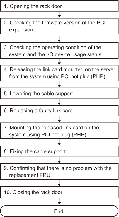
Active Replacement (Replacing the Link Card Using PHP)
Use PCI hot plug (PHP) to release the link card mounted on a server from the system.
This can be done only when the link card is mounted on the SPARC M12-2/M12-2S/M10-4/M10-4S and the setting for the direct I/O function is disabled.
This can be done only when the link card is mounted on the SPARC M12-2/M12-2S/M10-4/M10-4S and the setting for the direct I/O function is disabled.
|
Figure 7-14 Active Replacement Flow (Replacing the Link Card Using PHP)
|
|
| Step | Task | Reference |
|---|---|---|
| 1 | Opening the rack door | |
| 2 | Checking the firmware version of the PCI expansion unit | "5.3 Checking the Firmware Version of the PCI Expansion Unit" |
| 3 | Checking the operating condition of the system and the I/O device usage status | "5.4.1 Checking the Operating Condition of the Physical Partition or Logical Domain" "5.4.2 Checking the Assignment Status of I/O Devices" |
| 4 | Releasing the link card mounted on the server from the system using PCI hot plug (PHP) | "5.5.1 Releasing the Link Card or PCIe Card Using PCI Hot Plug (PHP)" |
| 5 | Lowering the cable support | "9.8.1 Lowering the Cable Support" in the Fujitsu SPARC M12-2/M12-2S Service Manual "5.9.2 Lowering the cable support" in the Fujitsu M10-4/Fujitsu M10-4S/SPARC M10-4/SPARC M10-4S Service Manual |
| 6 | Replacing a faulty link card | "Chapter 12 Maintaining PCIe Cards" in the Fujitsu SPARC M12-2/M12-2S Service Manual "Chapter 8 Maintaining the PCI Express Cards" in the Fujitsu M10-4/Fujitsu M10-4S/SPARC M10-4/SPARC M10-4S Service Manual |
| 7 | Mounting the released link card on the system using PCI hot plug (PHP) | "6.3.1 Mounting a Link Card Using PCI Hot Plug (PHP)" |
| 8 | Fixing the cable support | "10.1.2 Securing the Cable Support" in the Fujitsu SPARC M12-2/M12-2S Service Manual "6.1.2 Fixing the cable support" in the Fujitsu M10-4/Fujitsu M10-4S/SPARC M10-4/SPARC M10-4S Service Manual |
| 9 | Confirming that there is no problem with the replacement FRU | "10.5.3 Checking the FRU Status After Maintenance" in the Fujitsu SPARC M12-2/M12-2S Service Manual "6.3.3 Checking the FRU status after maintenance" in the Fujitsu M10-4/Fujitsu M10-4S/SPARC M10-4/SPARC M10-4S Service Manual |
| 10 | Closing the rack door |
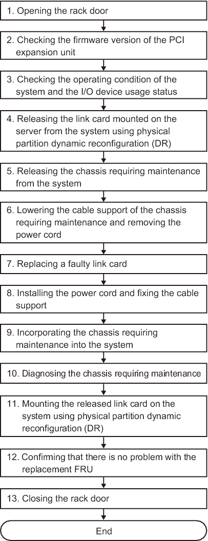
Active Replacement (Replacing the Link Card Using DR)
Release the link card mounted on the destination server from the system using physical partition dynamic reconfiguration (DR).
This can be done only when the link card is mounted on the SPARC M12-2S/M10-4S and the system has the building block configuration of the SPARC M12-2S/M10-4S.
This can be done only when the link card is mounted on the SPARC M12-2S/M10-4S and the system has the building block configuration of the SPARC M12-2S/M10-4S.
|
Figure 7-15 Active Replacement Flow (Replacing the Link Card Using DR)
|
|
| Step | Task | Reference |
|---|---|---|
| 1 | Opening the rack door | |
| 2 | Checking the firmware version of the PCI expansion unit | "5.3 Checking the Firmware Version of the PCI Expansion Unit" |
| 3 | Checking the operating condition of the system and the I/O device usage status | "5.4 Checking the Operating Condition and Resource Usage Status" |
| 4 | Releasing the link card mounted on the server from the system using physical partition dynamic reconfiguration (DR) | "5.5.2 Releasing the Link Card or PCIe Card Using Physical Partition Dynamic Reconfiguration (DR)" |
| 5 | Releasing the chassis requiring maintenance from the system | "9.6.1 Releasing the SPARC M12-2S From the Building Block Configuration" in the Fujitsu SPARC M12-2/M12-2S Service Manual "5.8.1 Releasing of the SPARC M10-4S chassis (possible only in a system with a building block configuration)" in the Fujitsu M10-4/Fujitsu M10-4S/SPARC M10-4/SPARC M10-4S Service Manual |
| 6 | Lowering the cable support of the chassis requiring maintenance and removing the power cord | "9.8 Accessing a FRU" in the Fujitsu SPARC M12-2/M12-2S Service Manual "5.9 Accessing a FRU" in the Fujitsu M10-4/Fujitsu M10-4S/SPARC M10-4/SPARC M10-4S Service Manual |
| 7 | Replacing a faulty link card | "Chapter 12 Maintaining PCIe Cards" in the Fujitsu SPARC M12-2/M12-2S Service Manual "Chapter 8 Maintaining the PCI Express Cards" in the Fujitsu M10-4/Fujitsu M10-4S/SPARC M10-4/SPARC M10-4S Service Manual |
| 8 | Installing the power cord and fixing the cable support | "10.1 Preparing Hardware" in the Fujitsu SPARC M12-2/M12-2S Service Manual "6.1 Restoring the Chassis" in the Fujitsu M10-4/Fujitsu M10-4S/SPARC M10-4/SPARC M10-4S Service Manual |
| 9 | Incorporating the chassis requiring maintenance into the system | "10.4 Incorporating a FRU Into the System" in the Fujitsu SPARC M12-2/M12-2S Service Manual "6.2.1 Incorporation of the SPARC M10-4S chassis (possible only in a system with a building block configuration)" in the Fujitsu M10-4/Fujitsu M10-4S/SPARC M10-4/SPARC M10-4S Service Manual |
| 10 | Diagnosing the chassis requiring maintenance | "10.5 Diagnosing a Replacement FRU" in the Fujitsu SPARC M12-2/M12-2S Service Manual "6.3.1 Diagnosing the system board" in the Fujitsu M10-4/Fujitsu M10-4S/SPARC M10-4/SPARC M10-4S Service Manual |
| 11 | Mounting the released link card on the system using physical partition dynamic reconfiguration (DR) | "6.3.2 Mounting the Link Card on the Server Using Physical Partition Dynamic Reconfiguration (DR)" |
| 12 | Confirming that there is no problem with the replacement FRU | "10.5.3 Checking the FRU Status After Maintenance" in the Fujitsu SPARC M12-2/M12-2S Service Manual "6.3.3 Checking the FRU status after maintenance" in the Fujitsu M10-4/Fujitsu M10-4S/SPARC M10-4/SPARC M10-4S Service Manual |
| 13 | Closing the rack door |
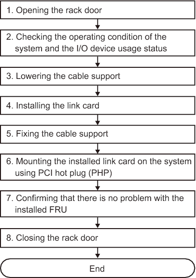
Active Addition (Installing the Link Card Using PHP)
Adding a link card to the server using PCI hot plug (PHP)
This can be done only when the server on which the link card is to be added is the SPARC M12-2/M12-2S/M10-4/M10-4S and the setting for the direct I/O function is disabled.
This can be done only when the server on which the link card is to be added is the SPARC M12-2/M12-2S/M10-4/M10-4S and the setting for the direct I/O function is disabled.
| Note - Active addition of the link card using PHP is supported by Oracle Solaris 11.2 SRU 11.2.2.8.0 or later. |
|
Figure 7-16 Active Addition Flow (Adding the Link Card Using PHP)
|
|
| Step | Task | Reference |
|---|---|---|
| 1 | Opening the rack door | |
| 2 | Checking the operating condition of the system and the I/O device usage status | "5.4.1 Checking the Operating Condition of the Physical Partition or Logical Domain" |
| 3 | Lowering the cable support | "9.8.1 Lowering the Cable Support" in the Fujitsu SPARC M12-2/M12-2S Service Manual "5.9.2 Lowering the cable support" in the Fujitsu M10-4/Fujitsu M10-4S/SPARC M10-4/SPARC M10-4S Service Manual |
| 4 | Installing the link card (*1) | "10.4 Installing a Link Card" |
| 5 | Fixing the cable support | "10.1.2 Securing the Cable Support" in the Fujitsu SPARC M12-2/M12-2S Service Manual "6.1.2 Fixing the cable support" in the Fujitsu M10-4/Fujitsu M10-4S/SPARC M10-4/SPARC M10-4S Service Manual |
| 6 | Mounting the added link card on the system using PCI hot plug (PHP) | "6.3.1 Mounting a Link Card Using PCI Hot Plug (PHP)" |
| 7 | Confirming that there is no problem with the added FRU | "10.5.3 Checking the FRU Status After Maintenance" in the Fujitsu SPARC M12-2/M12-2S Service Manual "6.3.3 Checking the FRU status after maintenance" in the Fujitsu M10-4/Fujitsu M10-4S/SPARC M10-4/SPARC M10-4S Service Manual |
| 8 | Closing the rack door | |
| *1 For details on the work for adding a PCI expansion unit, see the Installation Guide for your server. | ||
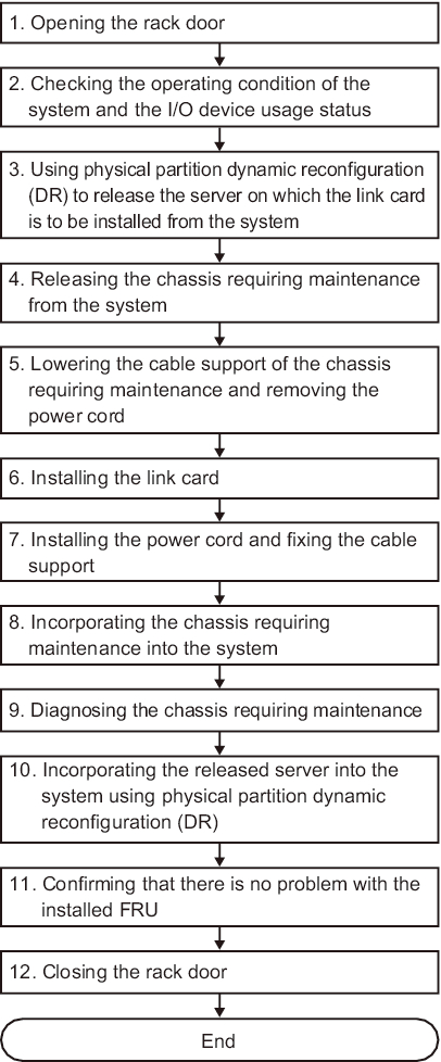
Active Addition (Adding the Link Card Using DR)
Adding the link card on the server using physical partition dynamic reconfiguration (DR)
This can be done only when the server on which the link card is to be added has the building block configuration of the SPARC M12-2S/M10-4S.
This can be done only when the server on which the link card is to be added has the building block configuration of the SPARC M12-2S/M10-4S.
|
Figure 7-17 Active Addition Flow (Adding the Link Card Using DR)
|
|
| Step | Task | Reference |
|---|---|---|
| 1 | Opening the rack door | |
| 2 | Checking the operating condition of the system and the I/O device usage status | "5.4 Checking the Operating Condition and Resource Usage Status" |
| 3 | Using physical partition dynamic reconfiguration (DR) to release the server on which the link card is to be added from the system | "5.5.2 Releasing the Link Card or PCIe Card Using Physical Partition Dynamic Reconfiguration (DR)" |
| 4 | Releasing the chassis requiring maintenance from the system | "9.6.1 Releasing the SPARC M12-2S From the Building Block Configuration" in the Fujitsu SPARC M12-2/M12-2S Service Manual "5.8.1 Releasing of the SPARC M10-4S chassis (possible only in a system with a building block configuration)" in the Fujitsu M10-4/Fujitsu M10-4S/SPARC M10-4/SPARC M10-4S Service Manual |
| 5 | Lowering the cable support of the chassis requiring maintenance and removing the power cord | "9.8 Accessing a FRU" in the Fujitsu SPARC M12-2/M12-2S Service Manual "5.9 Accessing a FRU" in the Fujitsu M10-4/Fujitsu M10-4S/SPARC M10-4/SPARC M10-4S Service Manual |
| 6 | Installing the link card (*1) | "Chapter 12 Maintaining PCIe Cards" in the Fujitsu SPARC M12-2/M12-2S Service Manual "Chapter 8 Maintaining the PCI Express Cards" in the Fujitsu M10-4/Fujitsu M10-4S/SPARC M10-4/SPARC M10-4S Service Manual |
| 7 | Installing the power cord and fixing the cable support | "10.1 Preparing Hardware" in the Fujitsu SPARC M12-2/M12-2S Service Manual "6.1 Restoring the Chassis" in the Fujitsu M10-4/Fujitsu M10-4S/SPARC M10-4/SPARC M10-4S Service Manual |
| 8 | Incorporating the chassis requiring maintenance into the system | "10.4 Incorporating a FRU Into the System" in the Fujitsu SPARC M12-2/M12-2S Service Manual "6.2.1 Incorporation of the SPARC M10-4S chassis (possible only in a system with a building block configuration)" in the Fujitsu M10-4/Fujitsu M10-4S/SPARC M10-4/SPARC M10-4S Service Manual |
| 9 | Diagnosing the chassis requiring maintenance | "10.5 Diagnosing a Replacement FRU" in the Fujitsu SPARC M12-2/M12-2S Service Manual "6.3.1 Diagnosing the system board" in the Fujitsu M10-4/Fujitsu M10-4S/SPARC M10-4/SPARC M10-4S Service Manual |
| 10 | Incorporating the released server into the system using physical partition dynamic reconfiguration (DR) | "6.3.2 Mounting the Link Card on the Server Using Physical Partition Dynamic Reconfiguration (DR)" |
| 11 | Confirming that there is no problem with the added FRU | "10.5.3 Checking the FRU Status After Maintenance" in the Fujitsu SPARC M12-2/M12-2S Service Manual "6.3.3 Checking the FRU status after maintenance" in the Fujitsu M10-4/Fujitsu M10-4S/SPARC M10-4/SPARC M10-4S Service Manual |
| 12 | Closing the rack door | |
| *1 For details on the work for adding a PCI expansion unit, see the Installation Guide for your server. | ||
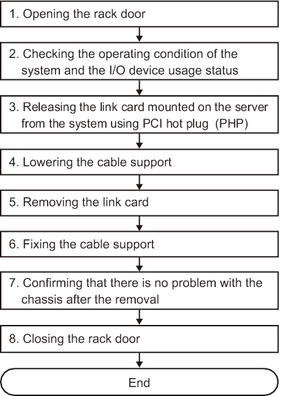
Active Removal (Removing the Link Card Using PHP)
Use PCI hot plug (PHP) to release the link card mounted on a server from the system.
This can be done only when the link card is mounted on the SPARC M12-2/M12-2S/M10-4/M10-4S and the setting for the direct I/O function is disabled.
This can be done only when the link card is mounted on the SPARC M12-2/M12-2S/M10-4/M10-4S and the setting for the direct I/O function is disabled.
|
Figure 7-18 Active Removal Flow (Removing the Link Card Using PHP)
|
|
| Step | Task | Reference |
|---|---|---|
| 1 | Opening the rack door | |
| 2 | Checking the operating condition of the system and the I/O device usage status | "5.4.1 Checking the Operating Condition of the Physical Partition or Logical Domain" "5.4.2 Checking the Assignment Status of I/O Devices" |
| 3 | Releasing the link card mounted on the server from the system using PCI hot plug (PHP) | "5.5.1 Releasing the Link Card or PCIe Card Using PCI Hot Plug (PHP)" |
| 4 | Lowering the cable support | "9.8.1 Lowering the Cable Support" in the Fujitsu SPARC M12-2/M12-2S Service Manual "5.9.2 Lowering the cable support" in the Fujitsu M10-4/Fujitsu M10-4S/SPARC M10-4/SPARC M10-4S Service Manual |
| 5 | Removing the link card | "Chapter 12 Maintaining PCIe Cards" in the Fujitsu SPARC M12-2/M12-2S Service Manual "Chapter 8 Maintaining the PCI Express Cards" in the Fujitsu M10-4/Fujitsu M10-4S/SPARC M10-4/SPARC M10-4S Service Manual |
| 6 | Fixing the cable support | "10.1.2 Securing the Cable Support" in the Fujitsu SPARC M12-2/M12-2S Service Manual "6.1.2 Fixing the cable support" in the Fujitsu M10-4/Fujitsu M10-4S/SPARC M10-4/SPARC M10-4S Service Manual |
| 7 | Confirming that there is no problem with the chassis after the removal | "10.5.3 Checking the FRU Status After Maintenance" in the Fujitsu SPARC M12-2/M12-2S Service Manual "6.3.3 Checking the FRU status after maintenance" in the Fujitsu M10-4/Fujitsu M10-4S/SPARC M10-4/SPARC M10-4S Service Manual |
| 8 | Closing the rack door |
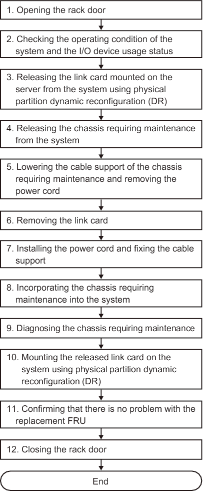
Active Removal (Removing the Link Card Using DR)
Release the link card mounted on the destination server from the system using physical partition dynamic reconfiguration (DR).
This can be done only when the link card is mounted on the SPARC M12-2S/M10-4S and the system has the building block configuration of the SPARC M12-2S/M10-4S.
This can be done only when the link card is mounted on the SPARC M12-2S/M10-4S and the system has the building block configuration of the SPARC M12-2S/M10-4S.
|
Figure 7-19 Active Replacement Flow (Replacing the Link Card Using DR)
|
|
| Step | Task | Reference |
|---|---|---|
| 1 | Opening the rack door | |
| 2 | Checking the operating condition of the system and the I/O device usage status | "5.4 Checking the Operating Condition and Resource Usage Status" |
| 3 | Releasing the link card mounted on the server from the system using physical partition dynamic reconfiguration (DR) | "5.5.2 Releasing the Link Card or PCIe Card Using Physical Partition Dynamic Reconfiguration (DR)" |
| 4 | Releasing the chassis requiring maintenance from the system | "9.6.1 Releasing the SPARC M12-2S From the Building Block Configuration" in the Fujitsu SPARC M12-2/M12-2S Service Manual "5.8.1 Releasing of the SPARC M10-4S chassis (possible only in a system with a building block configuration)" in the Fujitsu M10-4/Fujitsu M10-4S/SPARC M10-4/SPARC M10-4S Service Manual |
| 5 | Lowering the cable support of the chassis requiring maintenance and removing the power cord | "9.8 Accessing a FRU" in the Fujitsu SPARC M12-2/M12-2S Service Manual "5.9 Accessing a FRU" in the Fujitsu M10-4/Fujitsu M10-4S/SPARC M10-4/SPARC M10-4S Service Manual |
| 6 | Removing the link card | "Chapter 12 Maintaining PCIe Cards" in the Fujitsu SPARC M12-2/M12-2S Service Manual "Chapter 8 Maintaining the PCI Express Cards" in the Fujitsu M10-4/Fujitsu M10-4S/SPARC M10-4/SPARC M10-4S Service Manual |
| 7 | Installing the power cord and fixing the cable support | "10.1 Preparing Hardware" in the Fujitsu SPARC M12-2/M12-2S Service Manual "6.1 Restoring the Chassis" in the Fujitsu M10-4/Fujitsu M10-4S/SPARC M10-4/SPARC M10-4S Service Manual |
| 8 | Incorporating the chassis requiring maintenance into the system | "10.4 Incorporating a FRU Into the System" in the Fujitsu SPARC M12-2/M12-2S Service Manual "6.2.1 Incorporation of the SPARC M10-4S chassis (possible only in a system with a building block configuration)" in the Fujitsu M10-4/Fujitsu M10-4S/SPARC M10-4/SPARC M10-4S Service Manual |
| 9 | Diagnosing the chassis requiring maintenance | "10.5 Diagnosing a Replacement FRU" in the Fujitsu SPARC M12-2/M12-2S Service Manual "6.3.1 Diagnosing the system board" in the Fujitsu M10-4/Fujitsu M10-4S/SPARC M10-4/SPARC M10-4S Service Manual |
| 10 | Mounting the released link card on the system using physical partition dynamic reconfiguration (DR) | "6.3.2 Mounting the Link Card on the Server Using Physical Partition Dynamic Reconfiguration (DR)" |
| 11 | Confirming that there is no problem with the replacement FRU | "10.5.3 Checking the FRU Status After Maintenance" in the Fujitsu SPARC M12-2/M12-2S Service Manual "6.3.3 Checking the FRU status after maintenance" in the Fujitsu M10-4/Fujitsu M10-4S/SPARC M10-4/SPARC M10-4S Service Manual |
| 12 | Closing the rack door |
< Previous Page | Next Page >