
2.2.2 Rear LEDs on the PCI Expansion Unit
2.2.2 Rear LEDs on the PCI Expansion Unit
An LED is mounted on each component. If a component experiences an error, check the LEDs to see which component requires maintenance. Check the LEDs before starting maintenance work.
The following LEDs are mounted on the rear panel of the PCI expansion unit.
The following LEDs are mounted on the rear panel of the PCI expansion unit.
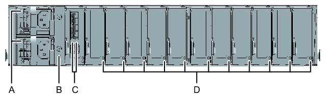
- Power supply units (A in Figure 2-6)
- I/O board (B in Figure 2-6)
- Link board (C in Figure 2-6)
- PCIe slots (D in Figure 2-6)
|
Figure 2-6 LEDs on the Chassis Rear
|
|
The LEDs mounted on each component and the statuses indicated by those LEDs are listed below.
| Name | Color | Status | Description |
|---|---|---|---|
| POWER/FAIL | Green | On | The input power is turned on and power is being supplied normally. |

|
Blinking (*) | Standby condition. | |
| Amber | On | Indicates that an error has occurred. | |
| Blinking (*) | Warning state (an error has occurred but the power unit is still operating). | ||
| Off | The input power is turned off. | ||
| * The blink interval is 1 second (1 Hz). | |||
| Name | Color | Status | Description |
|---|---|---|---|
| CHECK (Indicator) |
Amber | On | Indicates that an error has occurred. |

|
Blinking (*) | Indicates that the component requires maintenance. (This function is also referred to as the "locator.") | |
| Off | Indicates the normal state. Or, the breaker is open, or the power supply is otherwise off. | ||
| * The blink interval is 1 second (1 Hz). | |||
| Name | Color | Status | Description |
|---|---|---|---|
| LINK STATUS (PCI-Ex) /left side |
Green | On | The link is established with PCI-Express Gen3 x8. |
| Blinking (*) | The link is established with other than PCI-Express Gen3 x8 (degradation condition). | ||
| Off | The link is down. | ||
| LINK STATUS (Management) /right side |
Green | On | The management link is established. |
| Blinking (*) | The management link is disconnected. | ||
| Off | Indicates that power is not being supplied. | ||
| * The blink interval is 1 second (1 Hz). | |||
| Name | Color | Status | Description |
|---|---|---|---|
| POWER | Green | On | Indicates that power is being supplied. |

|
Off | Indicates that power is not being supplied. | |
| ATTENTION | Amber | On | Indicates that an error has occurred. |
|
|
Blinking (*) | Indicates that the component requires maintenance. (This function is also referred to as the "locator.") | |
| Off | Indicates the normal state. | ||
| * The blink interval is 1 second (1 Hz). | |||
< Previous Page | Next Page >