
7.3.2 Cold Removal
7.3.2 Cold Removal
This section describes the cold removal workflow.
References to detailed descriptions are written in the work procedure tables. See any of them as required.
References to detailed descriptions are written in the work procedure tables. See any of them as required.
Cold removal work varies depending on the method of releasing the link card mounted on the destination server. The following are the work patterns.
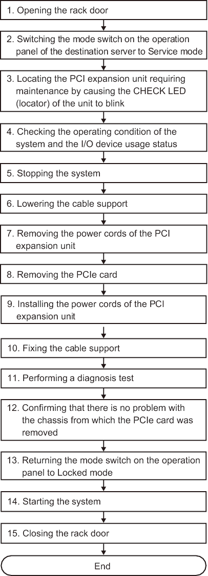
Cold Removal (Releasing the Link Card After Stopping the System)
Cold removal of a PCI Express card from the PCI expansion unit can be performed after stopping the system to which the PCI expansion unit is connected. This operation can be done when the connection destination of the PCI expansion unit is the SPARC M12-1/M12-2/M12-2S/M10-1/M10-4/M10-4S.
|
Figure 7-11 Cold Removal Flow (Releasing the Link Card After Stopping the System)
|
|
| Step | Task | Reference |
|---|---|---|
| 1 | Opening the rack door | |
| 2 | Switching the mode switch on the operation panel of the destination server to Service mode | "5.2 Switching the Mode Switch to Service Mode" in the Fujitsu SPARC M12-1 Service Manual "2.3.2 OPNL Control Function" in the Fujitsu SPARC M12-2/M12-2S Service Manual "5.2 Switching the Mode Switch to Service Mode" in the Fujitsu M10-1/SPARC M10-1 Service Manual "5.2 Switching the Mode Switch to Service Mode" in the Fujitsu M10-4/Fujitsu M10-4S/SPARC M10-4/SPARC M10-4S Service Manual |
| 3 | Locating the PCI expansion unit requiring maintenance by causing the CHECK LED (locator) of the unit to blink | "5.2 Checking the PCI Expansion Unit Requiring Maintenance and the Destination Physical Partition" |
| 4 | Checking the operating condition of the system and the I/O device usage status | "5.4.1 Checking the Operating Condition of the Physical Partition or Logical Domain" |
| 5 | Stopping the system | "5.5.3 Releasing the Link Card or PCIe Card After Stopping the System" |
| 6 | Lowering the cable support | "5.7.1 Lowering the Cable Support" |
| 7 | Removing the power cords of the PCI expansion unit | "5.7.2 Removing the Power Cord" |
| 8 | Removing the PCIe card | "Chapter 8 Maintaining the PCI Express Cards" |
| 9 | Installing the power cords of the PCI expansion unit | "6.1.2 Installing the Power Cords" |
| 10 | Fixing the cable support | "6.1.3 Fixing the Cable Support" |
| 11 | Performing a diagnosis test | "6.4 Diagnosing a Replacement FRU" in the Fujitsu SPARC M12-1 Service Manual "10.5 Diagnosing a Replacement FRU" in the Fujitsu SPARC M12-2/M12-2S Service Manual "6.4 Diagnosing a Replacement FRU" in the Fujitsu M10-1/SPARC M10-1 Service Manual "6.3 Diagnosing a Replacement FRU" in the Fujitsu M10-4/Fujitsu M10-4S/SPARC M10-4/SPARC M10-4S Service Manual |
| 12 | Confirming that there is no problem with the chassis from which the PCIe card was removed | "6.7 Checking the FRU Status After Maintenance" in the Fujitsu SPARC M12-1 Service Manual "10.5.3 Checking the FRU Status After Maintenance" in the Fujitsu SPARC M12-2/M12-2S Service Manual "6.7 Checking the FRU Status after Maintenance" in the Fujitsu M10-1/SPARC M10-1 Service Manual "6.3.3 Checking the FRU status after maintenance" in the Fujitsu M10-4/Fujitsu M10-4S/SPARC M10-4/SPARC M10-4S Service Manual |
| 13 | Returning the mode switch on the operation panel to Locked mode | "6.8 Returning the Mode Switch to Locked Mode" in the Fujitsu SPARC M12-1 Service Manual "2.3.2 OPNL Control Function" in the Fujitsu SPARC M12-2/M12-2S Service Manual "6.8 Returning the Mode Switch to Locked Mode" in the Fujitsu M10-1/SPARC M10-1 Service Manual "6.6 Returning the Mode Switch to Locked Mode" in the Fujitsu M10-4/Fujitsu M10-4S/SPARC M10-4/SPARC M10-4S Service Manual |
| 14 | Starting the system | "6.9 Starting the System" in the Fujitsu SPARC M12-1 Service Manual "10.9 Starting the System" in the Fujitsu SPARC M12-2/M12-2S Service Manual "6.9 Starting the System" in the Fujitsu M10-1/SPARC M10-1 Service Manual "6.8 Starting the Entire System" in the Fujitsu M10-4/Fujitsu M10-4S/SPARC M10-4/SPARC M10-4S Service Manual |
| 15 | Closing the rack door |
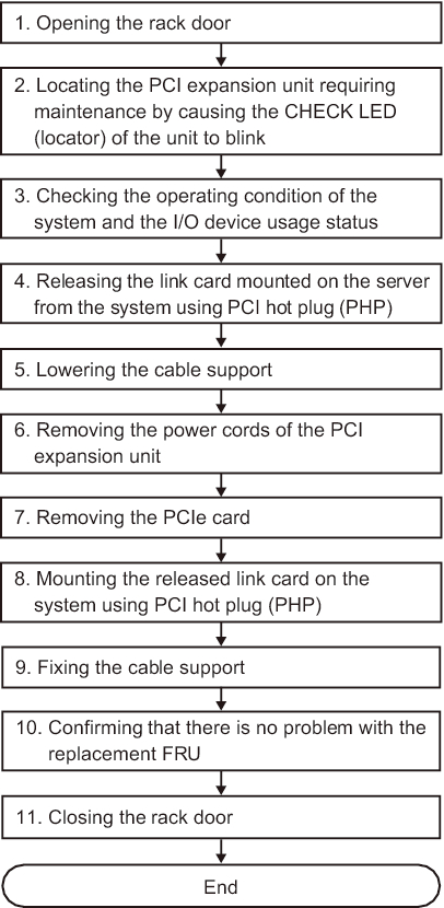
Cold Removal (Releasing the Link Card Using PHP)
Cold removal of a PCI Express card from the PCI expansion unit can be performed after releasing the link card mounted on the destination server from the system using PCI hot plug (PHP). This can be done only when the connection destination of the PCI expansion unit is the SPARC M12-2/M12-2S/M10-4/M10-4S and the setting for the direct I/O function is disabled.
|
Figure 7-12 Cold Removal Flow (Releasing the Link Card Using PHP)
|
|
| Step | Task | Reference |
|---|---|---|
| 1 | Opening the rack door | |
| 2 | Locating the PCI expansion unit requiring maintenance by causing the CHECK LED (locator) of the unit to blink | "5.2 Checking the PCI Expansion Unit Requiring Maintenance and the Destination Physical Partition" |
| 3 | Checking the operating condition of the system and the I/O device usage status | "5.4.1 Checking the Operating Condition of the Physical Partition or Logical Domain" "5.4.2 Checking the Assignment Status of I/O Devices" |
| 4 | Releasing the link card mounted on the server from the system using PCI hot plug (PHP) | "5.5.1 Releasing the Link Card or PCIe Card Using PCI Hot Plug (PHP)" |
| 5 | Lowering the cable support | "5.7.1 Lowering the Cable Support" |
| 6 | Removing the power cords of the PCI expansion unit | "5.7.2 Removing the Power Cord" |
| 7 | Removing the PCIe card | "Chapter 8 Maintaining the PCI Express Cards" |
| 8 | Mounting the released link card on the system using PCI hot plug (PHP) | "6.3.1 Mounting a Link Card Using PCI Hot Plug (PHP)" |
| 9 | Fixing the cable support | "6.1.3 Fixing the Cable Support" |
| 10 | Confirming that there is no problem with the replacement FRU | "10.5.3 Checking the FRU Status After Maintenance" in the Fujitsu SPARC M12-2/M12-2S Service Manual "6.3.3 Checking the FRU status after maintenance" in the Fujitsu M10-4/Fujitsu M10-4S/SPARC M10-4/SPARC M10-4S Service Manual |
| 11 | Closing the rack door |
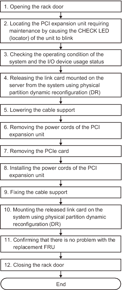
Cold Removal (Releasing the Link Card Using DR)
Cold removal of a PCI Express card from the PCI expansion unit can be performed after releasing the chassis in which the link card is mounted from the system using physical partition dynamic reconfiguration (DR). This can be done only when the connection destination of the PCI expansion unit has the building block configuration of the SPARC M12-2S/M10-4S.
|
Figure 7-13 Cold Removal Flow (Releasing the Link Card Using DR)
|
|
| Step | Task | Reference |
|---|---|---|
| 1 | Opening the rack door | |
| 2 | Locating the PCI expansion unit requiring maintenance by causing the CHECK LED (locator) of the unit to blink | "5.2 Checking the PCI Expansion Unit Requiring Maintenance and the Destination Physical Partition" |
| 3 | Checking the operating condition of the system and the I/O device usage status | "5.4 Checking the Operating Condition and Resource Usage Status" |
| 4 | Releasing the link card mounted on the server from the system using physical partition dynamic reconfiguration (DR) | "5.5.2 Releasing the Link Card or PCIe Card Using Physical Partition Dynamic Reconfiguration (DR)" |
| 5 | Lowering the cable support | "5.7.1 Lowering the Cable Support" |
| 6 | Removing the power cords of the PCI expansion unit | "5.7.2 Removing the Power Cord" |
| 7 | Removing the PCIe card | "Chapter 8 Maintaining the PCI Express Cards" |
| 8 | Installing the power cords of the PCI expansion unit | "6.1.2 Installing the Power Cords" |
| 9 | Fixing the cable support | "6.1.3 Fixing the Cable Support" |
| 10 | Mounting the released link card on the system using physical partition dynamic reconfiguration (DR) | "6.3.2 Mounting the Link Card on the Server Using Physical Partition Dynamic Reconfiguration (DR)" |
| 11 | Confirming that there is no problem with the replacement FRU | "10.5.3 Checking the FRU Status After Maintenance" in the Fujitsu SPARC M12-2/M12-2S Service Manual "6.3.3 Checking the FRU status after maintenance" in the Fujitsu M10-4/Fujitsu M10-4S/SPARC M10-4/SPARC M10-4S Service Manual |
| 12 | Closing the rack door |
< Previous Page | Next Page >