
2.1 Identifying the Names and Locations of Components
2.1 Identifying the Names and Locations of Components
This section describes the names and locations of each component.
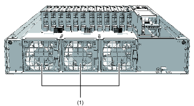
Components That Can be Accessed From the Front
|
Figure 2-1 Locations of Components That Can be Accessed From the Front
|
|
| Location No. | Component |
|---|---|
| 1 | Fan unit |
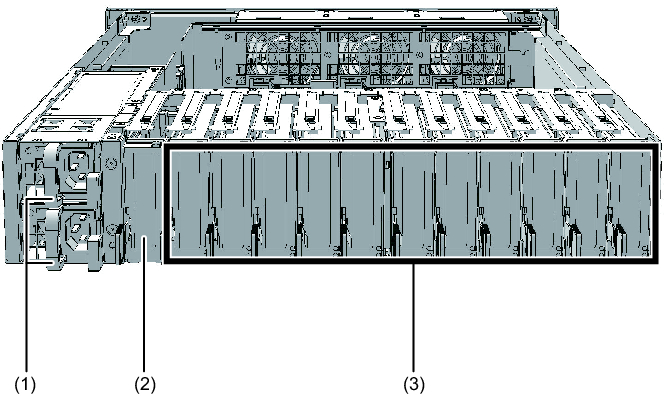
Components That Can be Accessed From the Rear
|
Figure 2-2 Locations of Components That Can be Accessed From the Rear
|
|
| Location No. | Component |
|---|---|
| 1 | Power supply unit |
| 2 | Link board (*) |
| 3 | PCI Express (PCIe) card |
| * The link board can be mounted only in its dedicated slot. | |
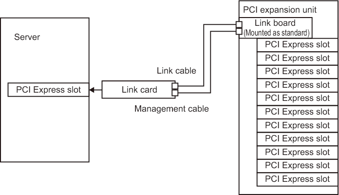
- Connecting the link board to the link card
Connect the link board mounted in the PCI expansion unit to the link card mounted in the SPARC M12-1/M12-2/M12-2S/M10-1/M10-4/M10-4S with the link cables and the management cable.
Figure 2-3 shows an example of the connection of the link board and the link card.
Figure 2-3 shows an example of the connection of the link board and the link card.
|
Figure 2-3 Example of Connection
|
|
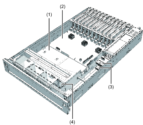
Internal Components
| Note - To access internal components, remove the PCI tray from the PCI expansion unit. For details on the procedure for removing the PCI tray, see "15.3 Removing the PCI Tray." |
|
Figure 2-4 Locations of Internal Components
|
|
| Location No. | Component |
|---|---|
| 1 | PCI tray |
| 2 | I/O board |
| 3 | PSU backplane |
| 4 | Fan backplane |
< Previous Page | Next Page >