4.2.1 Precautions for Replacement
4.2.1 Precautions for Replacement
This section describes the precautions for replacement.
Precautions for PCIe Card Replacement
- For active maintenance with PHP, a multipath setting is necessary depending on the use of the PCIe cards.
- To perform active maintenance using PHP, confirm that the card is PHP enabled. To do so, check "Appendix B Cards That Support PCI Hot Plug and Dynamic Reconfiguration" in the Fujitsu SPARC M12 PCI Card Installation Guide or "Appendix A Cards That Support PCI Hot Plug and Dynamic Reconfiguration" in the Fujitsu M10/SPARC M10 Systems PCI Card Installation Guide.
- If you perform active replacement by combining PHP with dynamic SR-IOV or the dynamic reconfiguration function for PCIe end point devices, see the following manual to check cards that support these functions.- "Appendix C Cards/On-Board Devices That Support SR-IOV" and "Appendix D Cards/On-Board Devices That Support Assignment of PCIe End Point Devices (PCIe Cards)" in the Fujitsu SPARC M12 PCI Card Installation Guide- "Appendix B Cards That Support SR-IOV" and "Appendix D Cards That Support the Dynamic Reassignment Function for the PCIe End Point Device (PCIe Card)" in the Fujitsu M10/SPARC M10 Systems PCI Card Installation Guide
Precautions for Link Card Replacement
- The replacement procedure for link cards is the same as the replacement procedure for PCIe cards at the server. See the service manual for each server.
- Before replacing the link card, check the firmware version. The firmware of the PCI expansion unit has been installed on the link card and the I/O board. When replacing the link card, you cannot get the firmware version on the replacement card to automatically match that on the replaced card. For this reason, confirm the firmware version beforehand since you will need it to match the firmware version of the replaced card. The PCI expansion unit sometimes cannot be recognized from the XSCF. In such cases, after replacing the link card, confirm the firmware version with a part that was not replaced. Then, match the firmware version of the replaced card.
- When you replace the I/O board and the link card at the same time, check the firmware version before the replacement. If you replace the I/O board and the link card at the same time without checking the firmware version, you may not be able to match the version.
- If multiple PCI expansion units are used and the firmware versions match within the combinations, there will be no problem with the operation even if firmware versions differ among PCI expansion units.
Note the following when mounting a link card using PHP.
- When mounting the link card on the system using PHP, do so with the PCIe card of the PCI expansion unit pulled out.
Precautions for Link Cable Replacement
- Do not place any heavy objects on the link cables.
- When performing replacement, replace the two link cables as a set.
- Do not bend the link cables unduly. Excessive bending could damage the link cables. The allowable bending radius for each link cable is shown below.
Link cable (electrical): Static/dynamic 40 mm (1.6 in.) or greater
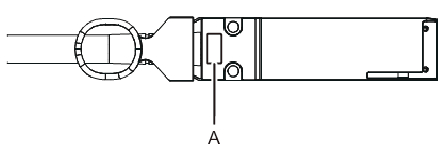
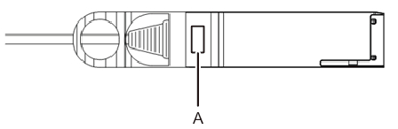
Link cable (optical): Static 35 mm (1.4 in.) or greater/dynamic 58 mm (2.3 in.) or greater - Before use, confirm that labels are affixed to the connectors at both ends of the link cable. The labels are affixed at the location of A shown in Figure 4-2 and Figure 4-3.
|
Figure 4-2 Label Location on a Link Cable (Electrical)
|
|
|
Figure 4-3 Label Location on a Link Cable (Optical)
|
|
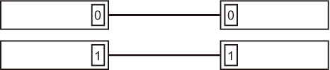
- If there is no label, affix one of the labels supplied with the link cable. The numbers on the labels affixed to the connectors at both ends of the link cable have to be the same (0 or 1).
|
Figure 4-4 State of Labels When Correctly Attached
|
|
Notes on Power Supply Unit Replacement
- Hot maintenance is supported only for a redundant configuration.
- The power supply has a redundant configuration featuring two units. Thus, the system can continue to function even if one of these units fails. The system should not, however, be operated for an extended period with one failed unit.
- When multiple power supply units are to be replaced, perform the replacement one by one. If redundancy of the power supply units cannot be secured, cold maintenance must be executed.
- Do not force a power supply unit into its slot. Using excessive force may damage the component or the chassis.
Precautions for Fan Unit Replacement
- When replacing multiple fan units, replace no more than one at a time. If the redundancy of the fan units cannot be secured, system-stopped maintenance must be executed.
- The fan units have a redundant configuration; therefore, even if one fan unit fails, the system can continue operating. Do not, however, operate the system for an extended period with a failed fan unit. Replace the failed fan unit as quickly as possible.
Precautions for I/O Board Replacement
- Before replacing the I/O board, check the firmware version. The firmware of the PCI expansion unit has been installed on the link card and the I/O board. When replacing the I/O board, you cannot get the firmware version on the replacement board to automatically match that on the replaced board. For this reason, confirm the firmware version beforehand since you will need it to match the firmware version of the replaced board. The PCI expansion unit sometimes cannot be recognized from the XSCF. In such cases, after replacing the I/O board, confirm the firmware version with a part that was not replaced. Then, match the firmware version of the replaced board.
- When you replace the I/O board and the link card at the same time, check the firmware version before the replacement. If you replace the I/O board and the link card at the same time without checking the firmware version, you may not be able to match the version.
- Do not replace the I/O board and the fan backplane at the same time. When you replace the I/O board and the fan backplane at the same time, all the serial numbers of the PCI expansion unit are changed to 0 ("0000000000"). If all these serial numbers are changed to 0 ("0000000000"), use the ioxadm command of the XSCF firmware to restore the serial numbers. If you replace both the I/O board and the fan backplane, replace either one. Then, start the physical partition connected to the PCI expansion unit to check the error log information on the PCI expansion unit. After confirming that no error log information is displayed, replace the other Field Replaceable Unit (FRU).
- If multiple PCI expansion units are used and they are combined such that their firmware versions match, there will be no problem with the operation even if the PCI expansion units are using different firmware versions.
Precautions for Updating the Firmware
- Always read the latest Product Notes.
- It is not possible to update the firmware on more than one unit at a time. Update the firmware on one at a time.
- The firmware can be updated if any of the following conditions are met when the system is operating and the PCI expansion unit can be recognized from the XSCF.- The PCI expansion unit is displayed when executing the ioxadm command.- The control domain to which the PCI expansion unit is connected is started and runs until the OpenBoot PROM state is set.
- Do not perform any power operation on the system during firmware update. To reflect the applied firmware, restart the physical partition or the I/O domain to which the PCI expansion unit belongs, or power cycle the system.
- If multiple PCI expansion units are being used and are combined in such a way that their firmware versions match, there will be no problem with their operation even if some of the PCI expansion units use different firmware versions.
< Previous Page | Next Page >