A.6.1 Configuration Example
A.6.1 Configuration Example
This section describes an example of configuring a control domain consisting of two SPARC M10-4S, i.e. two system boards (PSB<BB>) (2BB configuration).
To enable physical partition dynamic reconfiguration, it is necessary to establish a redundant configuration for the system volume disks and the network interfaces of the control domain by connecting the physical I/O of each SPARC M10-4S. This is done to make it possible to continue operation with the physical I/O of the remaining SPARC M10-4Ss when a SPARC M10-4S is removed.
To enable physical partition dynamic reconfiguration, it is necessary to establish a redundant configuration for the system volume disks and the network interfaces of the control domain by connecting the physical I/O of each SPARC M10-4S. This is done to make it possible to continue operation with the physical I/O of the remaining SPARC M10-4Ss when a SPARC M10-4S is removed.
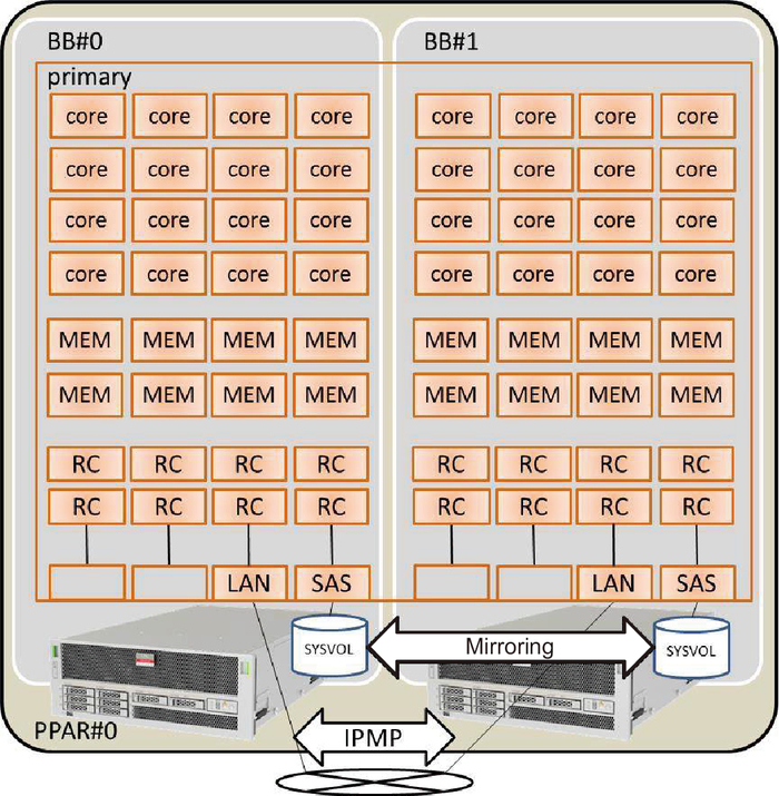
The following is a schematic diagram of a configuration that satisfies the above conditions. Moreover, the I/O configuration of each logical domain is simplified.
|
Figure A-8 Configuration Example of a 2BB Configuration Where All the Resources are Assigned
|

|
Figure A-8 shows a configuration example of a 2BB configuration where all the CPU cores, memory, and physical I/Os are assigned to the control domain. Therefore, the CPU cores and memory mounted on the SPARC M10-4S to be disconnected through physical partition dynamic reconfiguration are to be deleted, being unable to be moved at SPARC M10-4S release.
< Previous Page | Next Page >