6.4 Example of Operations for Moving a System Board
6.4 Example of Operations for Moving a System Board
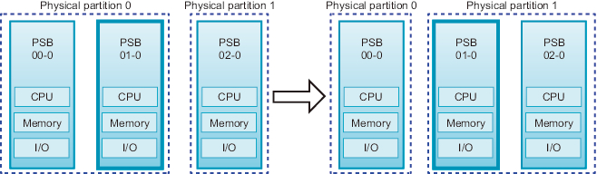
This section describes an example of the operations for moving a system board (PSB) between physical partitions as shown in Figure 6-9.
|
Figure 6-9 Example of Operations for Moving a System Board
|
|
The operation for moving a PSB between physical partitions comprises the combined operations of PSB unassignment and incorporation.
If the dynamic reconfiguration operation is not possible due to the operation status of the source physical partition, delete the PSB from the source physical partition by unassigning the PSB or reserving the unassignment of the PSB. When the dynamic reconfiguration operation is not possible at the destination physical partition, add the PSB by assigning the PSB or reserving the assignment of the PSB to the destination physical partition.
If the dynamic reconfiguration operation is not possible due to the operation status of the source physical partition, delete the PSB from the source physical partition by unassigning the PSB or reserving the unassignment of the PSB. When the dynamic reconfiguration operation is not possible at the destination physical partition, add the PSB by assigning the PSB or reserving the assignment of the PSB to the destination physical partition.
| Note - Suppose that the PPAR DR function of a physical partition is disabled, and the physical partition is operating. In such a case, you cannot release a PSB by specifying the -c disconnect or -c unassign option, or incorporate a PSB by specifying the -c configure option. |
The operation example here assumes that the source and destination physical partitions allow the dynamic reconfiguration operation. The operation example of the SPARC M10-4S presented here uses XSCF shell commands and the ldm command of Logical Domains Manager, which is management software of Oracle VM Server for SPARC. The same operations are also used for the SPARC M12-2S.
- Log in to the XSCF.
- Connect to the control domain console of the physical partition.
- Execute the ldm list-domain command to check the operation status of the logical domain.
- The following example shows that the control domain, two guest domains, and one root domain are operating.
| # ldm list-domain NAME STATE FLAGS CONS VCPU MEMORY UTIL UPTIME primary active -n-cv- UART 14 8G 64% 2h 54m guest0 active -n---- 5000 16 8G 42% 2h 54m guest1 active -n---- 5001 16 8G 11% 2h 54m domain01 active -n---- 5002 16 8G 7.3% 2h 54m |
- Execute the ldm list-devices command with the -a option specified to check the resource usage status.
- In the following example, the -a option is specified to display all resources bound to the logical domain and all resources that are not bound.
| # ldm list-devices -a CORE ID %FREE CPUSET 0 0 (0, 1) 4 0 (8, 9) 8 0 (16, 17) (Omitted) 184 0 (368, 369) 188 100 (376, 377) 512 100 (1024, 1025) 516 100 (1032, 1033) 520 100 (1040, 1041) 524 100 (1048, 1049) (Omitted) VCPU PID %FREE PM 0 0 no 1 0 no 8 0 no 9 0 no (Omitted) 369 0 no 376 100 --- 377 100 --- 1024 100 --- 1025 100 --- 1032 100 --- 1033 100 --- (Omitted) |
- Execute the ldm list-io command to check the usage status of the I/O devices.
In the following example, primary, which is a control domain, and domain01, which is a root domain, use I/O devices.
| # ldm list-io NAME TYPE BUS DOMAIN STATUS ---- ---- --- ------ ------ PCIE0 BUS PCIE0 primary IOV PCIE1 BUS PCIE1 primary IOV PCIE2 BUS PCIE2 primary IOV PCIE3 BUS PCIE3 primary IOV PCIE8 BUS PCIE8 domain01 IOV PCIE9 BUS PCIE9 domain01 IOV PCIE10 BUS PCIE10 domain01 IOV PCIE11 BUS PCIE11 domain01 IOV /BB0/CMUL/NET0 PCIE PCIE0 primary OCC /BB0/CMUL/NET2 PCIE PCIE0 primary OCC /BB0/CMUL/SASHBA PCIE PCIE0 primary OCC /BB0/PCI0 PCIE PCIE1 primary EMP /BB0/PCI1 PCIE PCIE1 primary EMP (Omitted) |
- Among the services provided by the root domain, release all I/O devices on the PSB to be deleted.
- In the following example, domain01, which is a root domain, is stopped, and of the PCIe root complexes owned by domain01, those related to the PSB to be deleted are released.
| Note - To reconfigure dynamically, the ldm stop-domain command to stop the root domain is not required. Start operation from the I/O device release. |
| # ldm stop-domain domain01 # ldm remove-io PCIE11 domain01 # ldm remove-io PCIE10 domain01 # ldm remove-io PCIE9 domain01 # ldm remove-io PCIE8 domain01 # ldm unbind-domain domain01 |
- Execute the ldm list-io command again to check the usage status of the I/O devices.
| # ldm list-io NAME TYPE BUS DOMAIN STATUS ---- ---- --- ------ ------ PCIE0 BUS PCIE0 primary IOV PCIE1 BUS PCIE1 primary IOV PCIE2 BUS PCIE2 primary IOV PCIE3 BUS PCIE3 primary IOV PCIE8 BUS PCIE8 PCIE9 BUS PCIE9 PCIE10 BUS PCIE10 PCIE11 BUS PCIE11 /BB0/CMUL/NET0 PCIE PCIE0 primary OCC /BB0/CMUL/NET2 PCIE PCIE0 primary OCC /BB0/CMUL/SASHBA PCIE PCIE0 primary OCC /BB0/PCI0 PCIE PCIE1 primary EMP /BB0/PCI1 PCIE PCIE1 primary EMP (Omitted) |
- Execute the deleteboard command with the -c unassign option specified to release the PSB from the physical partition.
- In the following example, PSB 01-0 is released from the physical partition, and is placed in the system board pool state.
| XSCF> deleteboard -c unassign 01-0 |
- Execute the showresult command to check the exit status of the deleteboard command just executed.
- In the following example, exit status of 0 is returned, indicating normal termination of the deleteboard command.
| XSCF> showresult 0 |
- Execute the showboards command to check the PSB status.
- The following example shows that PSB 01-0 is in the system board pool state.
| XSCF> showboards -a PSB PPAR-ID(LSB) Assignment Pwr Conn Conf Test Fault ---- ------------ ----------- ---- ---- ---- ------- -------- 00-0 00(00) Assigned y y y Passed Normal 01-0 SP Available n n n Passed Normal 02-0 01(00) Assigned y y y Passed Normal |
- Execute the ldm list-domain command on the control domain console of the source physical partition to confirm that the operation status of the logical domain has not changed after the deletion of the PSB.
- Execute the showpcl command to check the current physical partition configuration information (PPAR configuration information) of the destination physical partition.
| XSCF> showpcl -p 1 PPAR-ID LSB PSB Status 01 Running 00 00-0 |
- Execute the setpcl command to register the PSB in the PPAR configuration information of the destination physical partition.
In the following example, PSB 01-0 is mapped to logical system board (LSB 1) of physical partition 1.
| XSCF> setpcl -p 1 -a 1=01-0 |
- Execute the showpcl command to check the PPAR configuration information that has been set.
| XSCF> showpcl -p 1 PPAR-ID LSB PSB Status 01 Running 00 02-0 01 01-0 |
- Connect to the control domain console of the physical partition.
- Execute the ldm list-domain command to check the operation status of the logical domain.
- The following example shows the control domain and three guest domains in operation.
| # ldm list-domain NAME STATE FLAGS CONS VCPU MEMORY UTIL UPTIME primary active -n-cv- UART 14 8G 64% 2h 54m guest0 active -n---- 5000 16 8G 42% 2h 54m guest1 active -n---- 5001 16 8G 11% 2h 54m guest2 active -n---- 5002 16 8G 7.3% 2h 54m |
- Return to the XSCF shell, and execute the showcod command to check the CPU core resources assigned to the physical partition.
The following example displays the setting information for the CPU core resources.
As shown here, the system has 192 mounted CPU core resources, 128 CPU Activations registered in physical partition 0, and 64 CPU Activations registered in physical partition 1.
| XSCF> showcod -v -s cpu PROC Permits installed : 192 cores PROC Permits assigned for PPAR 0: 128 [Permanent 128cores] PROC Permits assigned for PPAR 1: 64 [Permanent 64cores] PROC Permits assigned for PPAR 2: 0 [Permanent 0cores] PROC Permits assigned for PPAR 3: 0 [Permanent 0cores] PROC Permits assigned for PPAR 4: 0 [Permanent 0cores] PROC Permits assigned for PPAR 5: 0 [Permanent 0cores] PROC Permits assigned for PPAR 6: 0 [Permanent 0cores] PROC Permits assigned for PPAR 7: 0 [Permanent 0cores] PROC Permits assigned for PPAR 8: 0 [Permanent 0cores] PROC Permits assigned for PPAR 9: 0 [Permanent 0cores] PROC Permits assigned for PPAR 10: 0 [Permanent 0cores] PROC Permits assigned for PPAR 11: 0 [Permanent 0cores] PROC Permits assigned for PPAR 12: 0 [Permanent 0cores] PROC Permits assigned for PPAR 13: 0 [Permanent 0cores] PROC Permits assigned for PPAR 14: 0 [Permanent 0cores] PROC Permits assigned for PPAR 15: 0 [Permanent 0cores] |
- Execute the showcodusage command to check the CPU core resource information.
The result shows that the mounting status is as follows.
[Physical partition 0]- Number of CPU core resources: 64- Number of registered CPU Activations: 128- Number of CPU core resources in use: 64
[Physical partition 1]- Number of CPU core resources: 64- Number of registered CPU Activations: 64- Number of CPU core resources in use: 64
[Entire system]- Number of CPU Activations currently not in use (Unused): 64
| XSCF> showcodusage -p ppar PPAR-ID/Resource In Use Installed Assigned ---------------- ------ --------- -------------- 0 - PROC 64 64 128 cores 1 - PROC 64 64 64 cores Unused - PROC 0 0 64 cores Note: Please confirm the value of the "In Use" by the ldm command of Oracle VM Server for SPARC. The XSCF may take up to 20 minutes to reflect the "In Use" of logical domains. |
| Note - If the number of registered CPU Activations is not enough for the number of CPUs to be used, purchase CPU Activations and add the CPU Activation keys. For details on how to add a CPU Activation key, see "Chapter 5 CPU Activation" in the Fujitsu SPARC M12 and Fujitsu M10/SPARC M10 System Operation and Administration Guide. |
- Execute the setcod command to assign the CPU core resources to the destination physical partitions.
- The following example reduces the number of assigned CPU Activations in physical partition 0 by removing 64 of them and adding them to physical partition 1.
| XSCF> setcod -p 0 -s cpu -c del 64 PROC Permits assigned for PPAR 0 : 128 -> 64 PROC Permits assigned for PPAR will be changed. Continue? [y|n] :y Completed. XSCF> setcod -p 1 -s cpu -c add 64 PROC Permits assigned for PPAR 1 : 64 -> 128 PROC Permits assigned for PPAR will be changed. Continue? [y|n] :y Completed. |
| Note - XSCF firmware of versions XCP 2250 and earlier do not support the -c add, -c delete, and -c set options. Specify the options of the setcod command as shown below to interactively add and delete CPU core resources. XSCF> setcod -s cpu |
- Execute the showboards command to check the PSB status.
| XSCF> showboards -a PSB PPAR-ID(LSB) Assignment Pwr Conn Conf Test Fault ---- ------------ ----------- ---- ---- ---- ------- -------- 00-0 00(00) Assigned y y y Passed Normal 01-0 SP Available n n n Passed Normal 02-0 01(00) Assigned y y y Passed Normal |
- Execute the addboard command with the -c configure option specified to incorporate the PSB into the physical partition.
- In the following example, PSB 01-0 is incorporated into physical partition 1.
| XSCF> addboard -c configure -p 1 01-0 |
- Execute the showresult command to check the exit status of the addboard command just executed.
- In the following example, exit status of 0 is returned, indicating normal termination of the addboard command.
| XSCF> showresult 0 |
- Execute the showboards command to check the PSB status.
- The next example shows "y" in the [Conn] and [Conf] columns for PSB 01-0, indicating that the PSB has been added correctly.
| XSCF> showboards -a PSB PPAR-ID(LSB) Assignment Pwr Conn Conf Test Fault ---- ------------ ----------- ---- ---- ---- ------- -------- 00-0 00(00) Assigned y y y Passed Normal 01-0 01(01) Assigned y y y Passed Normal 02-0 01(00) Assigned y y y Passed Normal |
- Execute the ldm list-domain command on the control domain console of the destination physical partition to confirm that the operation status of the logical domain has not changed after the addition of the PSB.
- Assign the physical partition resources in the logical domain to reconfigure the logical domain.
< Previous Page | Next Page >