2.4.1 Consideration of Logical Domain Configuration
2.4.1 Consideration of Logical Domain Configuration
This section describes what should be considered when configuring a logical domain.
Consideration of the number of logical domains
The maximum number of logical domains that can be configured is the same as the number of virtual CPUs (threads) that can be assigned to logical domains. Also, the maximum number of logical domains in each physical partition is limited by software. Table 2-4 lists, by model, the maximum number of logical domains that can be configured.
| Model | Maximum Number of Logical Domains |
|---|---|
| SPARC M12-1 | 48 |
| SPARC M12-2 | 192 |
| SPARC M12-2S | Number of threads per physical partition or 256, whichever the smaller |
| SPARC M10-1 | 32 |
| SPARC M10-1 (3.7 GHz) | 16 |
| SPARC M10-4 | 128 |
| SPARC M10-4 (3.7 GHz) | 64 |
| SPARC M10-4S | Number of threads per physical partition or 256, whichever the smaller |
Normally, assign virtual CPUs to a logical domain in units of cores.
Before creating more logical domains than the number of cores in a physical partition, perform verification such as an operation test.
Before creating more logical domains than the number of cores in a physical partition, perform verification such as an operation test.
Considerations when using the automatic replacement function for CPUs
You need to consider the CPU configuration when using the automatic replacement function for CPUs, which is supported by Oracle VM Server for SPARC 3.0 and later. For details, see "10.7 Setting Automatic Replacement of Failed CPU Cores" in the Fujitsu SPARC M12 and Fujitsu M10/SPARC M10 System Operation and Administration Guide.
Operation of the Logical Domains DR daemon
To assign hardware resources to a logical domain, the Logical Domains DR daemon (drd) must be operating on the control domain that manages the logical domain. For details of the drd daemon, see the Oracle VM Server for SPARC Reference Manual.
Registration of a CPU Activation key
Before a CPU core is assigned to a logical domain, it must be made available by assigning the CPU Activation key registered in the XSCF to the physical partition.
CPU Activation key is provided on the CD-ROM labeled "<model name> CPU Activation" supplied for server deployment. Have the CD-ROM on hand before registering a CPU Activation key.
The CPU Activation keys are contained in text files in the "ACTIVATION_KEY" folder on the CD-ROM. A file for registering the keys as a batch (XXXXX_XX.TXT) and another for registering them one at a time (XXXXX_XX_001.TXT, etc.) are provided. Use either file as needed for the situation.
| Note - The XSCF for system deployment may already contain CPU Activation keys. The registered keys would be the same as those included on the CD-ROM that comes with the system. In this case, you do not have to register the keys to the XSCF. |
| Note - If the number of CPU cores made available by the CPU Activation keys decreases, reassign CPU cores so that the number of CPU cores assigned to physical partitions is the number of available CPU cores or less. |
Notes on initial settings of the control domain
Do not use the memory dynamic reconfiguration (DR) function of the ldm command when making the initial settings of the control domain. Use delayed reconfiguration mode for the initial settings of the control domain. The mode reflects the configuration information through a logical domain restart.
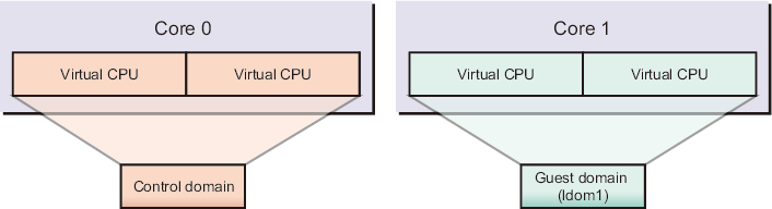
Unit of virtual CPU assignment
Although virtual CPUs can be assigned in units of cores or threads, we recommend you normally assign them in units of cores. Figure 2-4 shows an example of normal assignment.
|
Figure 2-4 Example of Normal Assignment
|
|
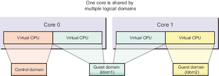
You should note that performance may deteriorate in cases where virtual CPUs are not assigned in units of cores. Figure 2-5 shows an example of performance deterioration.
|
Figure 2-5 Example of Undesirable Assignment
|
|
CPU core ID specification
To assign or delete a named core by specifying a CPU core ID (CID) for a logical domain using the ldm command, you need to set the CID while understanding its relationship with the physical location of the CPU core.
| Note - If you specify a CID to assign a CPU core to a logical domain, you cannot use the following functions. Make the settings after sufficiently understanding the content. - Dynamic reconfiguration of CPUs - Automatic replacement function for CPUs - CPU Dynamic Resource Management (DRM) |
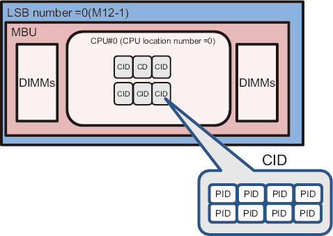
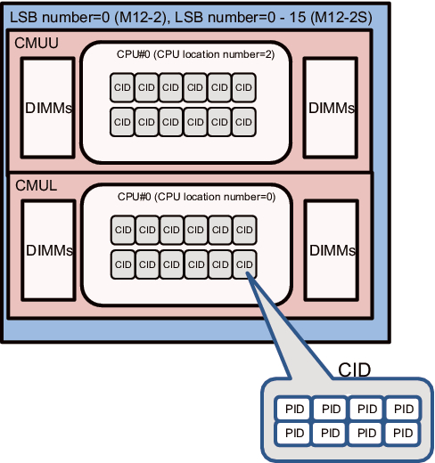
In Oracle VM Server for SPARC, a core ID (CID) is determined by the physical CPU number (PID) and the number of threads.
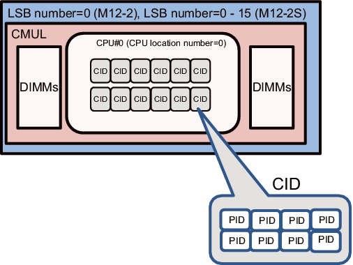
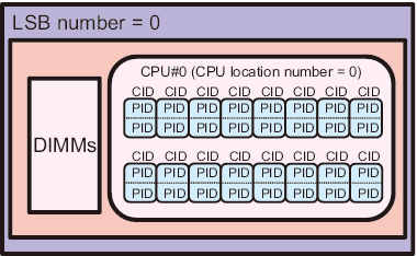
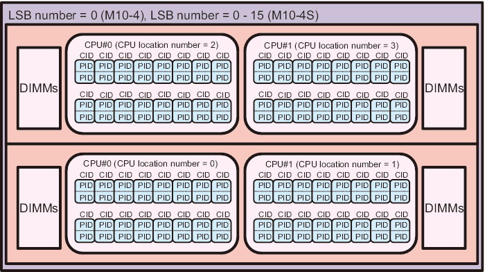
The following figures show the physical locations of the CPUs in each model of the SPARC M12/M10.
|
Figure 2-6 SPARC M12-1 CPU Locations
|
|
|
Figure 2-7 CPU Locations of the SPARC M12-2 or SPARC M12-2S (1 CPU Installed)
|
|
|
Figure 2-8 CPU Locations of the SPARC M12-2 or SPARC M12-2S (2 CPU Installed)
|
|
|
Figure 2-9 SPARC M10-1 CPU Locations
|
|
|
Figure 2-10 CPU Locations of the SPARC M10-4 or SPARC M10-4S (2 CPUs Installed)
|
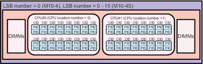 CPU Locations of the SPARC M10-4 or SPARC M10-4S (2 CPUs Installed)"/> CPU Locations of the SPARC M10-4 or SPARC M10-4S (2 CPUs Installed)"/>
|
|
Figure 2-11 CPU Locations of the SPARC M10-4 or SPARC M10-4S (4 CPUs Installed)
|
|
For the SPARC M12/M10 system, the relationship between the physical location of a CPU and a CID is as follows.
In this section, as a parameter that indicates the location of the CPU, a CPU serial number on the logical system board (LSB) is called a CPU location number.
| PID = LSB number x 1024 + CPU location number x 256 + CPU core number x 8 + thread number CID = PID / number of threads |
The range of each number used in the above formula is shown below.
| Number Type | Range |
|---|---|
| LSB number | 0 to 15 (*1) |
| CPU location number | 0, 2 (*2) |
| CPU core number | 0, 1, 2, 4, 5, 6, 8, 9, 10, 12, 13, 14 (0, 1, 2, 4, 5, 6) (*3) |
| Thread number | 0 to 7 |
| Number of threads | 8 |
| *1 For SPARC M12-1/M12-2, the LSB number is fixed to 0. For SPARC M12-2S, the LSB number can be set with the setpcl command of the XSCF firmware. *2 When one CPU is installed in SPARC M12-1/M12-2 or SPARC M12-2S, the CPU location number is 0. When two CPUs are installed, the CPU#0 for CMUL is 0, and the CPU#0 for CMUU is 2. *3 The figures in parentheses are the CPU core numbers of the SPARC M12-1. |
|
| Number Type | Range |
|---|---|
| LSB number | 0 to 15 (*1) |
| CPU location number | 0 to 3 (*2) |
| CPU core number | 0 to 15 (0 to 7) (*3) |
| Thread number | 0 to 1 |
| Number of threads | 2 |
| *1 For SPARC M10-1 and M10-4, the LSB number is fixed to 0. For SPARC M10-4S, the LSB number can be set with the setpcl command of the XSCF firmware. *2 When two CPUs are installed in SPARC M10-4 or M10-4S, the CPU location numbers are 0 to 1. When four CPUs are installed, the CPU location numbers are as follows: CMUL CPU#0 and #1 are 0 and 1, respectively, and CMUU CPU#0 and #1 are 2 and 3, respectively. *3 The figures in parentheses are the CPU core numbers when SPARC64 X+ 8-core 3.7 GHz processors are mounted in SPARC M10-1/M10-4. |
|
| Model | LSB Number | CPU Location Number |
PID | CID |
|---|---|---|---|---|
| SPARC M12-1 | 0 | 0 | 0 to 55 |
0 to 6 |
| SPARC M12-2 | 0 | 0 | 0 to 119 |
0 to 14 |
| 2 | 512 to 631 |
64 to 78 |
||
| SPARC M12-2S | 0 | 0 | 0 to 119 |
0 to 14 |
| 2 | 512 to 631 |
64 to 78 |
||
| 1 | 0 | 1024 to 1143 | 128 to 142 |
|
| 2 | 1536 to 1655 | 192 to 206 |
||
| 2 | 0 | 2048 to 2167 | 256 to 270 |
|
| 2 | 2560 to 2679 | 320 to 334 |
||
| 3 | 0 | 3072 to 3191 | 384 to 398 |
|
| 2 | 3584 to 3703 | 448 to 462 |
||
| 4 | 0 | 4096 to 4215 | 512 to 526 |
|
| 2 | 4608 to 4727 | 576 to 590 |
||
| 5 | 0 | 5120 to 5239 | 640 to 654 |
|
| 2 | 5632 to 5751 | 704 to 718 |
||
| 6 | 0 | 6144 to 6263 | 768 to 782 |
|
| 2 | 6656 to 6775 | 832 to 846 |
||
| 7 | 0 | 7168 to 7287 | 896 to 910 |
|
| 2 | 7680 to 7799 | 960 to 974 |
||
| 8 | 0 | 8192 to 8311 | 1024 to 1038 | |
| 2 | 8704 to 8823 | 1088 to 1102 | ||
| 9 | 0 | 9216 to 9335 | 1152 to 1166 | |
| 2 | 9728 to 9847 | 1216 to 1230 | ||
| 10 | 0 | 10240 to 10359 | 1280 to 1294 | |
| 2 | 10752 to 10871 | 1344 to 1358 | ||
| 11 | 0 | 11264 to 11383 | 1408 to 1422 | |
| 2 | 11776 to 11895 | 1472 to 1486 | ||
| 12 | 0 | 12288 to 12407 | 1536 to 1550 | |
| 2 | 12800 to 12919 | 1600 to 1614 | ||
| 13 | 0 | 13312 to 13431 | 1664 to 1678 | |
| 2 | 13824 to 13943 | 1728 to 1742 | ||
| 14 | 0 | 14336 to 14455 | 1792 to 1806 | |
| 2 | 14848 to 14967 | 1856 to 1870 | ||
| 15 | 0 | 15360 to 15479 | 1920 to 1934 | |
| 2 | 15872 to 15991 | 1984 to 1998 |
| Model | LSB Number | CPU Location Number | PID | CID |
|---|---|---|---|---|
| SPARC M10-1 | 0 | 0 | 0 to 121 (0 to 57) (*1) |
0 to 60 (0 to 28) (*1) |
| SPARC M10-4 | 0 | 0 1 2 3 |
0 to 121 (0 to 57) (*1) 256 to 377 (256 to 313) (*1) 512 to 633 (512 to 569) (*1) 768 to 889 (768 to 825) (*1) |
0 to 60 (0 to 28) (*1) 128 to 188 (128 to 156) (*1) 256 to 316 (256 to 284) (*1) 384 to 444 (384 to 412) (*1) |
| SPARC M10-4S | 0 | 0 1 2 3 |
0 to 121 256 to 377 512 to 633 768 to 889 |
0 to 60 128 to 188 256 to 316 384 to 444 |
| SPARC M10-4S | 1 | 0 1 2 3 |
1024 to 1145 1280 to 1401 1536 to 1657 1792 to 1913 |
512 to 572 640 to 700 768 to 828 896 to 956 |
| SPARC M10-4S | 2 | 0 1 2 3 |
2048 to 2169 2304 to 2425 2560 to 2681 2816 to 2937 |
1024 to 1084 1152 to 1212 1280 to 1340 1408 to 1468 |
| SPARC M10-4S | 3 | 0 1 2 3 |
3072 to 3193 3328 to 3449 3584 to 3705 3840 to 3961 |
1536 to 1596 1664 to 1724 1792 to 1852 1920 to 1980 |
| SPARC M10-4S | 4 | 0 1 2 3 |
4096 to 4217 4352 to 4473 4608 to 4729 4864 to 4985 |
2048 to 2108 2176 to 2236 2304 to 2364 2432 to 2492 |
| SPARC M10-4S | 5 | 0 1 2 3 |
5120 to 5241 5376 to 5497 5632 to 5753 5888 to 6009 |
2560 to 2620 2688 to 2748 2816 to 2876 2944 to 3004 |
| SPARC M10-4S | 6 | 0 1 2 3 |
6144 to 6265 6400 to 6521 6656 to 6777 6912 to 7033 |
3072 to 3132 3200 to 3260 3328 to 3388 3456 to 3516 |
| SPARC M10-4S | 7 | 0 1 2 3 |
7168 to 7289 7424 to 7545 7680 to 7801 7936 to 8057 |
3584 to 3644 3712 to 3772 3840 to 3900 3968 to 4028 |
| SPARC M10-4S | 8 | 0 1 2 3 |
8192 to 8313 8448 to 8569 8704 to 8825 8960 to 9081 |
4096 to 4156 4224 to 4284 4352 to 4412 4480 to 4540 |
| SPARC M10-4S | 9 | 0 1 2 3 |
9216 to 9337 9472 to 9593 9728 to 9849 9984 to 10105 |
4608 to 4668 4736 to 4796 4864 to 4924 4992 to 5052 |
| SPARC M10-4S | 10 | 0 1 2 3 |
10240 to 10361 10496 to 10617 10752 to 10873 11008 to 11129 |
5120 to 5180 5248 to 5308 5376 to 5436 5504 to 5564 |
| SPARC M10-4S | 11 | 0 1 2 3 |
11264 to 11385 11520 to 11641 11776 to 11897 12032 to 12153 |
5632 to 5692 5760 to 5820 5888 to 5948 6016 to 6076 |
| SPARC M10-4S | 12 | 0 1 2 3 |
12288 to 12409 12544 to 12665 12800 to 12921 13056 to 13177 |
6144 to 6204 6272 to 6332 6400 to 6460 6528 to 6588 |
| SPARC M10-4S | 13 | 0 1 2 3 |
13312 to 13433 13568 to 13689 13824 to 13945 14080 to 14201 |
6656 to 6716 6784 to 6844 6912 to 6972 7040 to 7100 |
| SPARC M10-4S | 14 | 0 1 2 3 |
14336 to 14457 14592 to 14713 14848 to 14969 15104 to 15225 |
7168 to 7228 7296 to 7356 7424 to 7484 7552 to 7612 |
| SPARC M10-4S | 15 | 0 1 2 3 |
15360 to 15481 15616 to 15737 15872 to 15993 16128 to 16249 |
7680 to 7740 7808 to 7868 7936 to 7996 8064 to 8124 |
| *1 The figures in parentheses are the pid and cid when SPARC64 X+ 8-core 3.7 GHz processors are mounted in the SPARC M10-1/M10-4. | ||||
To check the CID and PID of the CPU not assigned to the logical domain, use the ldm list-devices core command.
The following example executes the ldm list-devices core command.
[ID] indicates the CPU core ID (CID), and [CPUSET] indicates the physical CPU number (PID) of the CPU associated with the CPU core ID.
The following example executes the ldm list-devices core command.
[ID] indicates the CPU core ID (CID), and [CPUSET] indicates the physical CPU number (PID) of the CPU associated with the CPU core ID.
| # ldm list-devices core CORE ID %FREE CPUSET 920 100 (1840, 1841) 924 100 (1848, 1849) 936 100 (1872, 1873) 940 100 (1880, 1881) 944 100 (1888, 1889) 948 100 (1896, 1897) CID PID |
To check the CID and PID of the CPU assigned to the logical domain, use the ldm list-domain -o core command.
The following example shows the CID and PID of the CPU core assigned to the control domain.
The following example shows the CID and PID of the CPU core assigned to the control domain.
| # ldm list-domain -o core primary NAME primary CORE CID CPUSET 0 (0, 1) 4 (8, 9) 8 (16, 17) --- Omitted --- 896 (1792, 1793) 900 (1800, 1801) 904 (1808, 1809) 908 (1816, 1817) 912 (1824, 1825) 916 (1832, 1833) CID PID |
Memory assignment guideline for the logical domain
Assign 4 GB or more of virtual memory to the logical domain.
Memory size of a logical domain
If dynamic reconfiguration is not used to change the memory of the logical domain, the size of memory to be assigned to the logical domain can be set in units of 4 MB.
If you need to use dynamic reconfiguration to change the memory of the logical domain, the size of memory to be assigned to the logical domain must be set in units of 256 MB.
If you need to use dynamic reconfiguration to change the memory of the logical domain, the size of memory to be assigned to the logical domain must be set in units of 256 MB.
Saving of logical domain configuration information
After the logical domain configuration is complete, save the logical domain configuration information to the XSCF. Also save the logical domain configuration information before performing work related to configuring the logical domain. Saving the configuration information before the work is performed ensures that the logical domain can be restored without fail to its pre-configuration state.
A hardware failure or the like may cause a loss of logical domain configuration information. Therefore, after changing guest domain configuration information, use the ldm command of Logical Domains Manager, which is management software for Oracle VM Server for SPARC, to acquire the guest domain configuration information, and keep it in a safe location. Replicate the acquired configuration information to a tape device or file server to protect against data loss from the disk. Using the ldm command, you can also reconfigure a guest domain based on the acquired configuration information. For details, see the Oracle VM Server for SPARC Administration Guide and Oracle VM Server for SPARC Reference Manual of the version used.
You can back up the configuration information saved on the XSCF. To back up the configuration information to a file, use the dumpconfig command of the XSCF firmware. To restore the configuration information from the backup file, use the restoreconfig command.
Specified items when configuring a logical domain
To configure a logical domain, you need to define various names and specify various resources and their numbers. The following list shows items that you should define or specify when configuring a logical domain. Determine these items before starting work.
- Name of the virtual console terminal collection and distribution unit
- Virtual disk server name
- Virtual switch service name
- Virtual network device interface name
- Virtual device name
- Virtual disk name
- Guest domain name
- Name for logical domain configuration information
- Range for virtual console terminal port numbers
- Device used with the virtual switch service
- Device used with the virtual disk service
- Number of CPUs assigned to a guest domain
- Size of memory assigned to a guest domain
- Port number of the virtual console terminal assigned to a guest domain
Order of shutdown of logical domains
To use the ordered shutdown function and specify the shutdown order of each logical domain with the poweroff command of the XSCF, set a shutdown group for the created guest domain. Shutdown groups specify the order of shutdown of logical domains.
The shutdown groups range from 0 to 15. The group with a larger number shuts down earlier. Guest domains belong to group 15 by default. The control domain always belongs to group 0, and this cannot be changed. Set the shutdown order by considering the dependency of logical domains.
The shutdown groups range from 0 to 15. The group with a larger number shuts down earlier. Guest domains belong to group 15 by default. The control domain always belongs to group 0, and this cannot be changed. Set the shutdown order by considering the dependency of logical domains.
< Previous Page | Next Page >