4.2 Configuring and Operating a Physical Partition
4.2 Configuring and Operating a Physical Partition
This section describes points to consider when configuring a physical partition, and a configuration example.
- How to determine the recommended physical partition number (PPAR-ID)
You can specify any number from 0 to 15, depending on the system configuration, as a PPAR-ID. However, the BB-ID of a chassis mounted in the SPARC M12/M10 system must be specified for the PPAR-ID. If the BB-ID of an unmounted chassis in the SPARC M12/M10 system is specified for the PPAR-ID, the physical partition will fail to power on and cannot be used.
For example, when the BB-IDs of the SPARC M12-2S/M10-4S units mounted on the system are BB#00, BB#01, BB#02, and BB#03, you can specify 0, 1, 2, or 3 as the PPAR-ID when configuring a physical partition.
- For efficient use of resources after the start of operation, you may remove a SPARC M12-2S/M10-4S unit. If the BB-ID of the SPARC M12-2S/M10-4S unit to be removed is the same number as a PPAR-ID in the system, you need to stop the physical partition. In that case, physical partition reconfiguration may be required. Therefore, we recommend considering the following when configuring physical partitions.
- [For a 2BB configuration]- When configuring a system with only one physical partition, set PPAR-ID 0. You can remove BB#01, which is a different number from the PPAR-ID.- When configuring a system with two physical partitions, assign BB#00 to PPAR-ID 0 and BB#01 to PPAR-ID 1.
- In this way, you can remove a SPARC M12-2S/M10-4S unit without stopping the physical partition of the SPARC M12-2S/M10-4S unit that should be kept in the system.
- Example: Configuring two physical partitions
[Recommended pattern]
Assign BB#00 to PPAR-ID 0 and BB#01 to PPAR-ID 1.
When a SPARC M12-2S/M10-4S unit is removed, the physical partition with a different number from the BB-ID of the removed unit is not affected.
PPAR-ID 0 [BB#00]
PPAR-ID 1 [BB#01]
[Non-recommended pattern]
Assign BB#01 to PPAR-ID 0 and BB#00 to PPAR-ID 1. When a SPARC M12-2S/M10-4S unit is removed, the physical partition of the unremoved unit also must be stopped.
As a result, physical partition reconfiguration is required.
PPAR-ID 0 [BB#01]
PPAR-ID 1 [BB#00]
- [For a 3BB or larger configuration with directly interconnected chassis]- When configuring a system with only one physical partition, set PPAR-ID 0. You can remove a SPARC M12-2S/M10-4S unit with a BB-ID different from the PPAR-ID.
- - When configuring a system with two or more physical partitions, do not set, as a PPAR-ID, the BB-ID of any SPARC M12-2S/M10-4S unit that may be removed (*1). So even when that SPARC M12-2S/M10-4S unit is removed, each physical partition with a different number from the BB-ID of the removed unit is not affected.
*1 The master and standby SPARC M12-2S/M10-4S units must be kept in the system after reduction. Therefore, the SPARC M12-2S/M10-4S unit that may be removed should have a BB-ID other than BB#00 or BB#01.
- In this way, you can remove the SPARC M12-2S/M10-4S unit without stopping the physical partition of the SPARC M12-2S/M10-4S unit that should be kept in the system.
- Example: Configuring two physical partitions in a 4BB configuration with directly interconnected chassis
[Recommended pattern 1: Supposing the reduction of resources of each physical partition]
Assign BB#00 and BB#02 to PPAR-ID 0 and BB#01 and BB#03 to PPAR-ID 1.
You can remove the SPARC M12-2S/M10-4S unit of BB#02 or BB#03, each of which is a different number from the PPAR-ID, without stopping either physical partition.
PPAR-ID 0 [BB#00 and BB#02]
PPAR-ID 1 [BB#01 and BB#03]
[Recommended pattern 2: Supposing the reduction of the number of physical partitions]
Assign BB#00 and BB#01 to PPAR-ID 0 and BB#02 and BB#03 to PPAR-ID 2.
You can remove the SPARC M12-2S/M10-4S unit of BB#02 or BB#03 without stopping the physical partition of the SPARC M12-2S/M10-4S unit that should be kept in the system.
PPAR-ID 0 [BB#00 and BB#01]
PPAR-ID 2 [BB#02 and BB#03]
[Non-recommended pattern]
Assign BB#00 and BB#01 to PPAR-ID 0 and BB#02 and BB#03 to PPAR-ID 1.
The SPARC M12-2S/M10-4S units at PPAR-ID 0 cannot be removed because they are the master and standby.
PPAR-ID 0 [BB#00 and BB#01]
PPAR-ID 1 [BB#02 and BB#03]
- [For a configuration with connections via a crossbar box]
When configuring a physical partition in a 2BB configuration or larger, do not set, as a PPAR-ID, the BB-ID of a SPARC M12-2S/M10-4S unit that may be removed.
In this way, you can remove a SPARC M12-2S/M10-4S unit without stopping the physical partition of the SPARC M12-2S/M10-4S unit that should be kept in the system.
The remainder of this section uses examples to describe a specific procedure for configuring two physical partitions in a configuration with four SPARC M10-4S units.
- Assignment of PSB (BB)
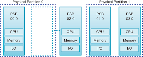
Assign system boards (PSB 00-0 and PSB 02-0) to physical partition 0, and assign system boards (PSB 01-0 and PSB 03-0) to physical partition 1. However, keep PSB 02-0 in an assignable state instead of actually assigning it. - Mirror mode setting (option)
Set memory mirroring only on PSB 00-0. - Configuration policy / memory nullification / I/O nullification
In this example, set the configuration policy to "system" for physical partitions 0 and 1, and do not use memory nullification and I/O nullification. - Physical partition operation mode
Set the message level of diagnosis messages to "normal."
Figure 4-2 is a conceptual diagram of configured physical partitions.
|
Figure 4-2 Conceptual Diagram of Configured Physical Partitions
|
|
- Log in to the XSCF shell with a user account that has the platadm privilege.
- Execute the setupfru command to set memory mirroring.
| XSCF> setupfru -m y sb 00-0 |
- Execute the showfru command as required to check the status of memory mirroring.
Check the status of memory mirroring on the system board (PSB 00-0). If "yes" appears in all of [Memory Mirror Mode], mirror mode is properly set.
| XSCF> showfru sb 00-0 Device Location Memory Mirror Mode sb 00-0 cpu 00-0-0 yes cpu 00-0-1 yes cpu 00-0-2 yes cpu 00-0-3 yes XSCF> |
- Execute the setpcl command to create physical partition configuration information (PPAR configuration information).
Map physical system boards PSB 00-0 and PSB 02-0 to logical system boards LSB 0 and LSB 1, respectively, of physical partition 0. Map physical system boards PSB 01-0 and PSB 03-0 to logical system boards LSB 0 and LSB 1, respectively, of physical partition 1. In this example, set the configuration policy to "system," and do not use memory nullification and I/O nullification.
| XSCF> setpcl -p 0 -a 0=00-0 1=02-0 XSCF> setpcl -p 0 -s policy=system XSCF> setpcl -p 0 -s no-mem=false XSCF> setpcl -p 0 -s no-io=false XSCF> setpcl -p 1 -a 0=01-0 1=03-0 XSCF> setpcl -p 1 -s policy=system XSCF> setpcl -p 1 -s no-mem=false XSCF> setpcl -p 1 -s no-io=false |
- Execute the showpcl command to check the contents of the PPAR configuration information.
[PPAR-ID] shows the physical partition number, [LSB] shows the logical system board number, and [PSB] shows the PSB number.
| XSCF> showpcl -v -a PPAR-ID LSB PSB Status No-Mem No-IO Cfg-policy 00 Powered Off System 00 00-0 False False 01 02-0 False False 01 Powered Off System 00 01-0 False False 01 03-0 False False |
- Execute the showboards command to check the PSB.
The PSB displayed with "SP" under [PPAR-ID] and "Available" under [Assignment] can be assigned. "SP" represents the system board pool state, which means that the board does not belong to any physical partition.
| XSCF> showboards -a PSB PPAR-ID(LSB) Assignment Pwr Conn Conf Test Fault ---- ------------ ----------- ---- ---- ---- ------- -------- 00-0 SP Available n n n Passed Normal 01-0 SP Available n n n Passed Normal 02-0 SP Available n n n Passed Normal 03-0 SP Available n n n Passed Normal |
- Execute the addboard command to assign the PSBs.
| XSCF> addboard -c assign -p 0 00-0 XSCF> addboard -c assign -p 1 01-0 03-0 |
- Execute the showboards command to check the PSB assigned status.
When the [R] column displays "*" (asterisk) for an assigned PSB, and the physical partitions and logical system boards (LSBs) are set as shown by the setting in the [PPAR-ID] column, the PSB is correctly assigned.
| XSCF> showboards -v -a PSB R PPAR-ID(LSB) Assignment Pwr Conn Conf Test Fault ---- - ------------ ----------- ---- ---- ---- ------- -------- 00-0 * 00(00) Assigned n n n Passed Normal 01-0 * 01(00) Assigned n n n Passed Normal 02-0 SP Available n n n Passed Normal 03-0 * 01(01) Assigned n n n Passed Normal |
- Execute the showcodactivation command to check whether the CPU Activation key is registered in the system.
If only the header is displayed, the CPU Activation key is not registered in the XSCF. To add the CPU Activation key, perform the procedure from step 10. If an index number is displayed, the CPU Activation key is registered in the XSCF. To continue the procedure, go to step 13.
| XSCF> showcodactivation Index Description Count ------- ----------- ------ |
- Execute the addcodactivation command to register the CPU Activation key.
| XSCF> addcodactivation "Product: SPARC M10-4S SequenceNumber: 10005 Cpu: noExpiration 2 Text-Signature-SHA256-RSA2048: PSSrElBrse/r69AVSVFd38sT6AZm2bxeUDdPQHKbtxgvZPsrtYguqiNUieB+mTDC : : b1GCkFx1RH27FdVHiB2H0A==" Above Key will be added, Continue?[y|n]:y |
- Execute the showcodactivation command to check the contents of the added CPU Activation key.
If executing the command displays the number of CPU Activations for the purchased resources, the CPU Activation key has been correctly registered.
| XSCF> showcodactivation Index Description Count ------- ----------- ------ 0 PROC 2 1 PROC 2 2 PROC 2 3 PROC 2 |
- Execute the setcod command to assign the CPU core resources to the physical partitions.
| XSCF> setcod -p 0 -s cpu -c set 4 PROC Permits assigned for PPAR 0 : 0 -> 4 PROC Permits assigned for PPAR will be changed. Continue? [y|n] :y Completed. XSCF> setcod -p 1 -s cpu -c set 4 PROC Permits assigned for PPAR 1 : 0 -> 4 PROC Permits assigned for PPAR will be changed. Continue? [y|n] :y Completed. |
| Note - XSCF firmware of versions XCP 2250 and earlier do not support the -c add, -c delete, and -c set options. Specify the options of the setcod command as shown below to interactively add and delete CPU core resources. XSCF> setcod -s cpu |
- Execute the resetdateoffset command to reset the difference between the time managed by the XSCF and the time managed by physical partitions.
| XSCF> resetdateoffset -p 0 XSCF> resetdateoffset -p 1 |
- Execute the setpparmode command and set the detail level of diagnosis messages to "normal."
| XSCF> setpparmode -p 0 -m message=normal XSCF> setpparmode -p 1 -m message=normal |
- Execute the poweron command to power on the physical partitions.
- The following example powers on physical partitions 0 and 1.
| XSCF> poweron -p 0 PPAR-IDs to power on:00 Continue? [y|n] :y 00 :Powering on *Note* This command only issues the instruction to power-on. The result of the instruction can be checked by the "showlogs power". XSCF> poweron -p 1 PPAR-IDs to power on:01 Continue? [y|n] :y 01 :Powering on *Note* This command only issues the instruction to power-on. The result of the instruction can be checked by the "showlogs power". |
- Execute the showboards command to check the PSB status.
If "y" appears in all the [Pwr], [Conn], and [Conf] columns, the physical partition is operating correctly.
| XSCF> showboards -a PSB PPAR-ID(LSB) Assignment Pwr Conn Conf Test Fault ---- ------------ ----------- ---- ---- ---- ------- -------- 00-0 00(00) Assigned y y y Passed Normal 01-0 01(00) Assigned y y y Passed Normal 02-0 SP Available n n n Passed Normal 03-0 01(01) Assigned y y y Passed Normal |
< Previous Page | Next Page >