1.1.3 Features of the Domain Configuration
1.1.3 Features of the Domain Configuration
This section describes the domain configuration, a feature of the SPARC M12/M10 system.
Features of a system consisting of logical domains
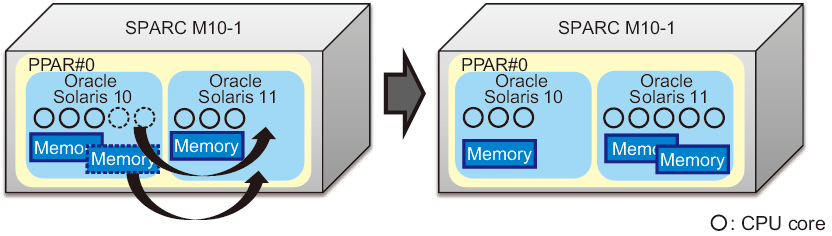
The SPARC M12/M10 system allows multiple logical domains to be configured using Oracle VM Server for SPARC and an independent OS to run on each logical domain. Different logical domains can run different versions of the OS, respectively. CPUs, memory, and I/Os can be assigned flexibly to each logical domain, enabling efficient use of hardware resources.
Figure 1-7 shows an example in which two CPU cores and a part of the memory resource are moved between Oracle Solaris instances of different versions.
|
Figure 1-7 Efficient Use of Hardware Resources between Logical Domains (Example of One-Unit Configuration Using SPARC M10-1)
|
|
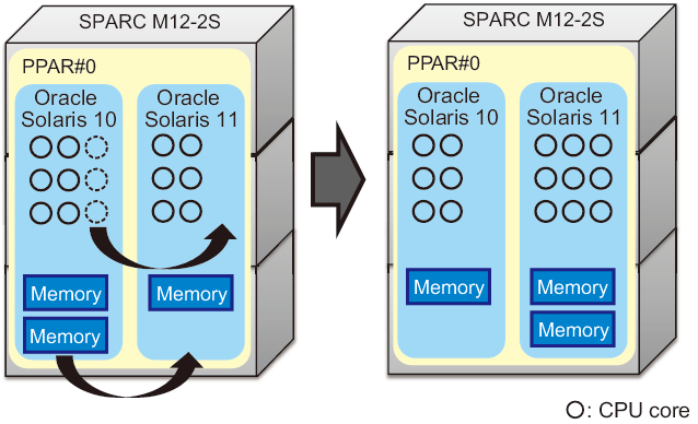
Figure 1-8 shows an example in which three CPU cores and one memory resource are moved between Oracle Solaris instances of different versions.
|
Figure 1-8 Efficient Use of Hardware Resources between Logical Domains (Building Block Configuration)
|
|
Features of a system consisting of physical partitions
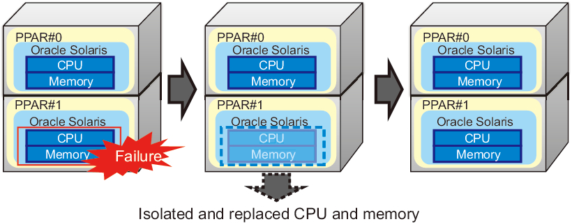
The SPARC M12-2S/M10-4S system allows physical partitions to be configured with one or more chassis and an independent OS to run on each physical partition.
A system consisting of physical partitions provides a higher level of hardware independence than a system that consists of logical domains using Oracle VM Sever for SPARC.
A system consisting of physical partitions provides a higher level of hardware independence than a system that consists of logical domains using Oracle VM Sever for SPARC.
Figure 1-9 shows an example in which chassis are isolated from the system to replace the CPU and memory.
|
Figure 1-9 Feature of Physical Partitions (Hardware Independence)
|
|
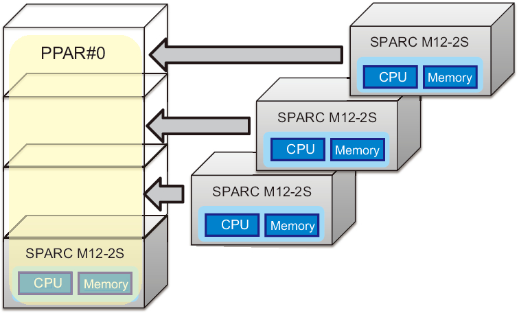
The SPARC M12-2S/M10-4S system allows hardware resources to be expanded by stacking multiple chassis. This enables a small system to be expanded gradually as necessary for the environment.
Figure 1-10 shows an example in which three SPARC M12-2S units are added and the four units are used as a single physical partition.
|
Figure 1-10 Feature of Physical Partitions (Hardware Scalability)
|
|
Also, CPUs, memory, and I/Os can be added to and removed from a physical partition in units of building blocks (PSBs).
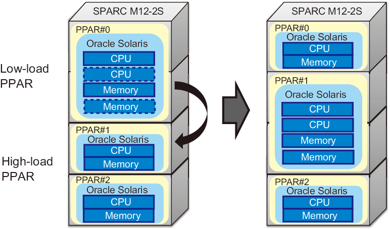
Moreover, a system consisting of multiple physical partitions allows these physical partitions to be managed in a centralized manner, and hardware resources can be moved from a physical partition with a low load to one with a high load.
Moreover, a system consisting of multiple physical partitions allows these physical partitions to be managed in a centralized manner, and hardware resources can be moved from a physical partition with a low load to one with a high load.
Figure 1-11 shows an example in which one chassis’s worth of resources is moved from PPAR#0 to PPAR#1.
|
Figure 1-11 Feature of Physical Partitions (Hardware Flexibility)
|
|
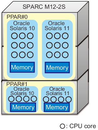
In addition, logical domains can be configured in each physical partition.
Figure 1-12 shows an example in which three SPARC M12-2S units are connected and two logical domains are configured in each of the two physical partitions.
|
Figure 1-12 Example of Configuring Logical Domains in Physical Partitions
|
|
< Previous Page | Next Page >