A.4.1 Configuration Example
A.4.1 Configuration Example
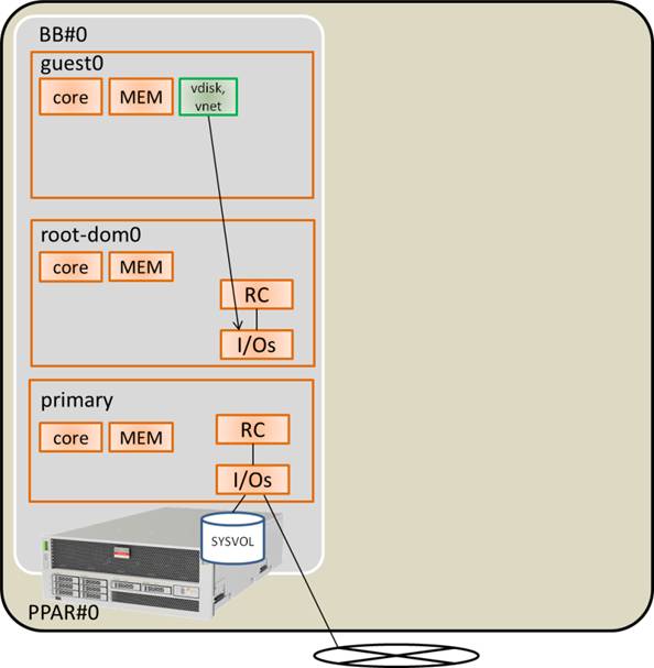
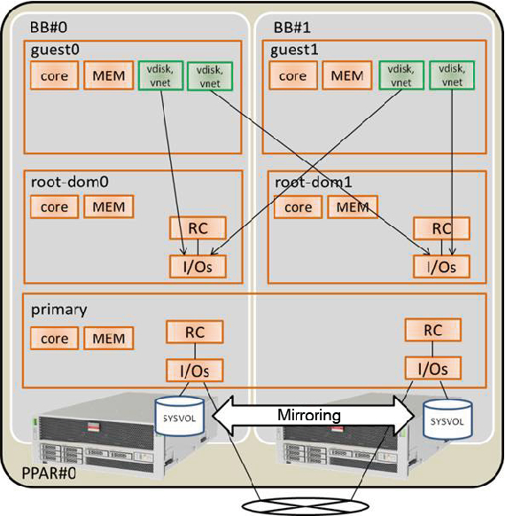
This section expands a SPARC M10-4S with a 1BB configuration to a 2BB configuration through physical partition dynamic reconfiguration and adds guest domain guest1 and root domain root-dom1 to which the root complexes of an expanded SPARC M10-4S (BB#1) have been assigned. This section also gives a configuration example in which the virtual I/O of each guest domain is made redundant and the system volume of the control domain is mirrored with the internal hard disk.
|
Figure A-4 Example of the 1BB Configuration (Before Expansion)
|
|
|
Figure A-5 Example of the Configuration After Expansion From 1BB to 2BB
|
|
| Logical Domain | Before Expansion | After Expansion | ||||
|---|---|---|---|---|---|---|
| CPU Core | Memory | I/O Configuration | CPU Core | Memory | I/O Configuration | |
| Control domain (primary) |
16 | 28 GB |
On-board #0 (PCIE0, PCIE4) |
32 | 56 GB |
On-board #0 (PCIE0, PCIE4) On-board #1 (PCIE8, PCIE12) |
| guest0 | 32 | 64 GB |
vdisk0, vnet0 | 32 | 64 GB |
vdisk0, vdisk10 vnet0, vnet10 |
| guest1 | - | - | - | 32 | 64 GB |
vdisk1, vdisk11 vnet1, vnet11 |
| root-dom0 | 16 | 32 GB |
PCIE1, PCIE2, PCIE3, PCIE5, PCIE6, PCIE7, vds0, vsw0 | 16 | 32 GB |
PCIE1, PCIE2, PCIE3, PCIE5, PCIE6, PCIE7, vds0, vsw0 |
| root-dom1 | - | - | - | 16 | 32 GB |
PCIE9, PCIE10, PCIE11, PCIE13, PCIE14, PCIE15, vds1, vsw1 |
| Unassigned resource | 0 | Approx. 2 GB(*1) |
- | 0 | Approx. 4.75 GB(*1) |
- |
| Total | 64 | 128 GB |
- | 128 | 256 GB |
- |
| *1 A memory region of approx. 2 GB or 1.25 GB on each SPARC M10-4S is assigned for the hypervisor. So, the memory resource that can be assigned to the logical domain is smaller than the physically mounted memory capacity. | ||||||
< Previous Page | Next Page >