A.5.1 Configuration Example
A.5.1 Configuration Example
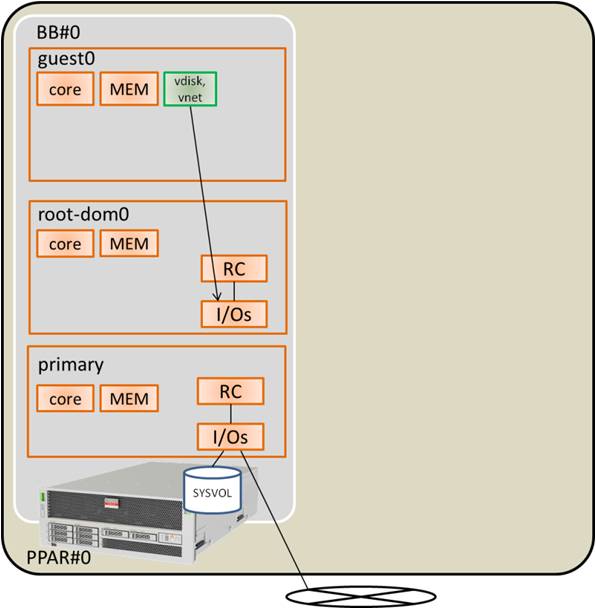
This section gives a configuration example in which a SPARC M10-4S with a SPARC64 X+ processor mounted is added to the physical partition configured with one SPARC M10-4S with a SPARC64 X processor mounted. This enables active replacement of each SPARC M10-4S.
To enable active replacement of the SPARC M10-4S with PPAR DR, the configuration must satisfy the following conditions.
To enable active replacement of the SPARC M10-4S with PPAR DR, the configuration must satisfy the following conditions.
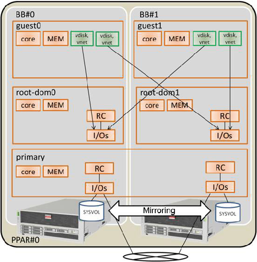
- It is necessary to create a redundant configuration by connecting I/O devices under the root complex on each SPARC M10-4S to the system volume I/O devices and the network of the control domain. This is done for the following reasons: When a SPARC M10-4S is removed, the I/O devices for the remaining SPARC M10-4Ss can be used to continue the operation even if an I/O configuration change is done by restarting the control domain.
- It is necessary to divide root domains for each SPARC M10-4S. This is done for the following reasons: When a SPARC M10-4S is removed, the status whereby it is impossible to use services provided by the physical I/O devices of other SPARC M10-4Ss must be avoided.
- It is necessary to operate the business with a guest domain consisting of virtual I/O devices (vdisk, vnet). This is done for the following reasons: The root domain is stopped at SPARC M10-4S removal and the physical I/O devices can be disconnected. Moreover, these operations will not influence the guest domain that is performing the operation.
|
Figure A-6 System Configuration Example (1BB Configuration: SPARC64 X Processor Mounted) (Before Expansion)
|
|
|
Figure A-7 Example of a System Configuration in Which PPAR DR is Possible (2BB Configuration: After Installation of the System Board Mounted on the SPARC64 X+ Processor)
|
|
| Logical Domain | Before Expansion | After Expansion | ||||
|---|---|---|---|---|---|---|
| CPU Core | Memory | I/O Configuration | CPU Core | Memory | I/O Configuration | |
| Control domain (primary) |
16 | 28 GB |
On-board #0 (PCIE0, PCIE4) |
32 | 56 GB |
On-board #0 (PCIE0, PCIE4) On-board #1 (PCIE8, PCIE12) |
| guest0 | 32 | 64 GB |
vdisk0, vnet0 | 32 | 64 GB |
vdisk0, vdisk10 vnet0, vnet10 |
| guest1 | - | - | - | 32 | 64 GB |
vdisk1, vdisk11 vnet1, vnet11 |
| root-dom0 | 16 | 32 GB |
PCIE1, PCIE2, PCIE3, PCIE5, PCIE6, PCIE7, vds0, vsw0 | 16 | 32 GB |
PCIE1, PCIE2, PCIE3, PCIE5, PCIE6, PCIE7, vds0, vsw0 |
| root-dom1 | - | - | - | 16 | 32 GB |
PCIE9, PCIE10, PCIE11, PCIE13, PCIE14, PCIE15, vds1, vsw1 |
| Unassigned resource | 0 | Approx. 2 GB(*1) |
- | 0 | Approx. 4.75 GB(*1) |
- |
| Total | 64 | 128 GB |
- | 128 | 256 GB |
- |
| *1 A memory region of approx. 2 GB or 1.25 GB on each SPARC M10-4S is assigned for the hypervisor. So, the memory resource that can be assigned to the logical domain is smaller than the physically mounted memory capacity. | ||||||
< Previous Page | Next Page >