7.2 Active Maintenance Flow
7.2 Active Maintenance Flow
This section explains the replacement workflows in the active state for the following FRUs mounted on the crossbar box.
- XSCF unit
- XSCF BB control cable
- XSCF DUAL control cable
- Power supply unit
- Fan unit
- Dedicated power distribution unit mounted on the rack for expanded connection
| Note - Maintenance is not available in the active/cold state for FRUs mounted on the crossbar box. In the active state, only hot maintenance is enabled. |
| Note - Active/Hot maintenance is enabled for an XSCF BB control cable used in the following connection. - Cable connecting crossbar boxes to each other |
| Note - Active/Cold maintenance is enabled for an XSCF BB control cable used in the following connection. - Cable connecting each chassis to the crossbar box in a configuration where one physical partition consists of chassis with two or more BBs |
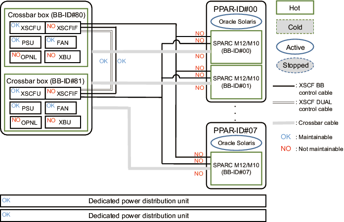
Figure 7-2 shows FRUs with active/hot maintenance enabled.
|
Figure 7-2 FRUs With Active/Hot Maintenance Enabled
|
|
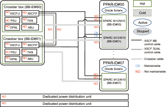
Figure 7-3 shows FRUs with active/cold maintenance enabled.
|
Figure 7-3 FRUs With Active/Cold Maintenance Enabled
|
|
For details on the connection routes of the XSCF BB control cable, XSCF DUAL control cable, and crossbar cable, see "Appendix B Cable Connection Information on Building Block Configurations" in the Fujitsu SPARC M12-2S Installation Guide or "Appendix B Cable Connection Information on Building Block Configurations" in the Fujitsu M10-4S/SPARC M10-4S Installation Guide.
Active maintenance has the following patterns:
- Active/Hot Replacement of the XSCF Unit
- Active/Hot Replacement of the XSCF DUAL Control Cable
- Active/Hot Replacement of the XSCF BB Control Cable (Connecting Crossbar Boxes to Each Other)
- Active/Cold Replacement of the XSCF BB Control Cable (Connecting the Crossbar Box to the Chassis of the SPARC M12-2S/M10-4S)
- Active/Hot Replacement of the Power Supply Unit
- Active/Hot Replacement of the Fan Unit
- Active/Hot Replacement of the Dedicated Power Distribution Unit
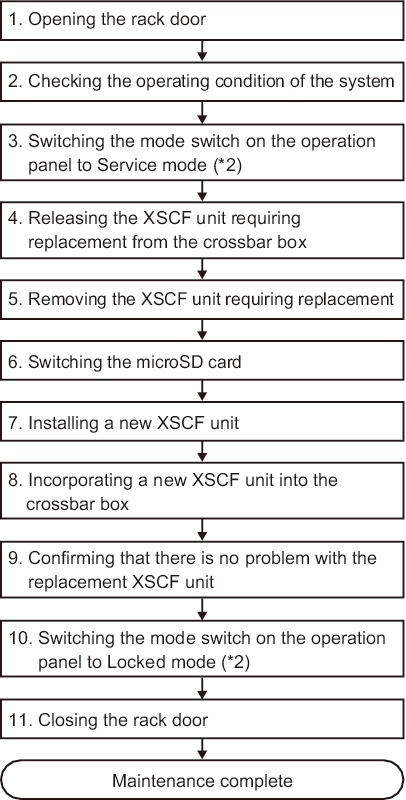
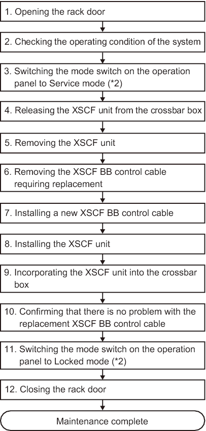
Active/Hot Replacement of the XSCF Unit
Active/Hot replacement can be performed on the XSCF unit. Perform the following procedure to replace it.
|
Figure 7-4 Flow of Active/Hot Replacement of the XSCF Unit (*1)
|
|
*1 The same procedure is used for inactive/hot replacement of the XSCF unit. *2 The mode switch on the operation panel does not need to be changed in active maintenance. |
| Item |
Work Procedure | Reference |
|---|---|---|
| 1 | Opening the rack door | |
| 2 | Checking the operating condition of the system | "5.2.1 Checking the Operating Condition of the Physical Partition or Logical Domain" |
| 3 | Switching the mode switch on the operation panel to Service mode (*2) | "5.2.2 Switching the Mode Switch to Service Mode" |
| 4 | Releasing the XSCF unit requiring replacement from the crossbar box | "5.4.1 Releasing FRUs of the Crossbar Box With the replacefru Command" |
| 5 | Removing the XSCF unit requiring replacement | "8.4 Removing the XSCF Unit" |
| 6 | Switching the microSD card (can be omitted if the microSD card is not switched) |
"8.5 Switching the microSD Card" |
| 7 | Installing a new XSCF unit | "8.6 Installing the XSCF Unit" |
| 8 | Incorporating a new XSCF unit into the crossbar box | "6.2.1 Restoring the Crossbar Box With the replacefru Command" |
| 9 | Confirming that there is no problem with the replacement XSCF unit | "6.3.2 Checking the FRU Status After Maintenance" |
| 10 | Switching the mode switch on the operation panel to Locked mode (*2) | "6.6 Returning the Mode Switch to Locked Mode" |
| 11 | Closing the rack door | |
| *1 The same procedure is used for inactive/hot replacement of the XSCF unit. *2 The mode switch on the operation panel does not need to be changed in active maintenance. |
||
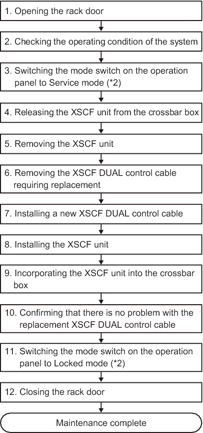
Active/Hot Replacement of the XSCF DUAL Control Cable
Active/Hot replacement can be performed on the XSCF DUAL control cable. Perform the following procedure to replace it.
|
Figure 7-5 Flow of Active/Hot Replacement of the XSCF DUAL Control Cable (*1)
|
|
*1 The same procedure is used for inactive/hot replacement of the XSCF DUAL control cable. *2 The mode switch on the operation panel does not need to be changed in active maintenance. |
| Item |
Work Procedure | Reference |
|---|---|---|
| 1 | Opening the rack door | |
| 2 | Checking the operating condition of the system | "5.2.1 Checking the Operating Condition of the Physical Partition or Logical Domain" |
| 3 | Switching the mode switch on the operation panel to Service mode (*2) | "5.2.2 Switching the Mode Switch to Service Mode" |
| 4 | Releasing the XSCF unit from the crossbar box | "5.4.1 Releasing FRUs of the Crossbar Box With the replacefru Command" |
| 5 | Removing the XSCF unit (*3) | "8.4 Removing the XSCF Unit" |
| 6 | Removing an XSCF DUAL control cable | "10.3 Removing an XSCF DUAL Control Cable" |
| 7 | Installing a new XSCF DUAL control cable | "10.4 Installing an XSCF DUAL Control Cable" |
| 8 | Installing the XSCF unit | "8.6 Installing the XSCF Unit" |
| 9 | Incorporating the XSCF unit into the crossbar box | "6.2.1 Restoring the Crossbar Box With the replacefru Command" |
| 10 | Confirming that there is no problem with the replacement XSCF DUAL control cable | "6.3.2 Checking the FRU Status After Maintenance" |
| 11 | Switching the mode switch on the operation panel to Locked mode (*2) | "6.6 Returning the Mode Switch to Locked Mode" |
| 12 | Closing the rack door | |
| *1 The same procedure is used for inactive/hot replacement of the XSCF DUAL control cable. *2 The mode switch on the operation panel does not need to be changed in active maintenance. *3 When you replace an XSCF DUAL control cable, you need to remove and then install the XSCF unit (pseudo replacement). Here, partially pull the XSCF unit out halfway. |
||
Active/Hot Replacement of the XSCF BB Control Cable (Connecting Crossbar Boxes to Each Other)
Active/Hot replacement can be performed on the XSCF BB control cable connecting crossbar boxes to each other. Perform the following procedure to replace it.
|
Figure 7-6 Flow of Active/Hot Replacement of the XSCF BB Control Cable (Connecting Crossbar Boxes to Each Other) (*1)
|
 Flow of Active/Hot Replacement of the XSCF BB Control Cable (Connecting Crossbar Boxes to Each Other) (*1)"/> Flow of Active/Hot Replacement of the XSCF BB Control Cable (Connecting Crossbar Boxes to Each Other) (*1)"/>
|
*1 The same procedure is used for inactive/hot replacement of the XSCF BB control cable. *2 The mode switch on the operation panel does not need to be changed in active maintenance. |
| Item |
Work Procedure | Reference |
|---|---|---|
| 1 | Opening the rack door | |
| 2 | Checking the operating condition of the system | "5.2.1 Checking the Operating Condition of the Physical Partition or Logical Domain" |
| 3 | Switching the mode switch on the operation panel to Service mode (*2) | "5.2.2 Switching the Mode Switch to Service Mode" |
| 4 | Releasing the XSCF unit from the crossbar box | "5.4.1 Releasing FRUs of the Crossbar Box With the replacefru Command" |
| 5 | Removing the XSCF unit (*3) | "8.4 Removing the XSCF Unit" |
| 6 | Removing the XSCF BB control cable requiring replacement | "9.3 Removing an XSCF BB Control Cable" |
| 7 | Installing a new XSCF BB control cable | "9.4 Installing an XSCF BB Control Cable" |
| 8 | Installing the XSCF unit | "8.6 Installing the XSCF Unit" |
| 9 | Incorporating the XSCF unit into the crossbar box | "6.2.1 Restoring the Crossbar Box With the replacefru Command" |
| 10 | Confirming that there is no problem with the replacement XSCF BB control cable | "6.3.2 Checking the FRU Status After Maintenance" |
| 11 | Switching the mode switch on the operation panel to Locked mode (*2) | "6.6 Returning the Mode Switch to Locked Mode" |
| 12 | Closing the rack door | |
| *1 The same procedure is used for inactive/hot replacement of the XSCF BB control cable. *2 The mode switch on the operation panel does not need to be changed in active maintenance. *3 When you replace an XSCF BB control cable, you need to remove and then install the XSCF unit (pseudo replacement). Here, partially pull the XSCF unit out halfway. |
||
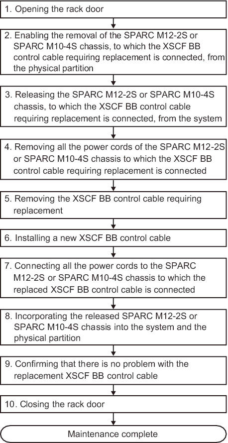
Active/Cold Replacement of the XSCF BB Control Cable (Connecting the Crossbar Box to the Chassis of the SPARC M12-2S/M10-4S)
Active/Cold replacement is enabled for an XSCF BB control cable connecting the crossbar box to the chassis of the SPARC M12-2S/M10-4S if it is possible to release the chassis by using PPAR DR. Perform the following procedure to replace it.
|
Figure 7-7 Flow of Active/Cold Replacement of the XSCF BB Control Cable (Connecting the Crossbar Box to the Chassis of the SPARC M12-2S/M10-4S)
|
 Flow of Active/Cold Replacement of the XSCF BB Control Cable (Connecting the Crossbar Box to the Chassis of the SPARC M12-2S/M10-4S)"/> Flow of Active/Cold Replacement of the XSCF BB Control Cable (Connecting the Crossbar Box to the Chassis of the SPARC M12-2S/M10-4S)"/>
|
| Item |
Work Procedure | Reference |
|---|---|---|
| 1 | Opening the rack door | |
| 2 | Enabling the removal of the SPARC M12-2S or SPARC M10-4S chassis, to which the XSCF BB control cable requiring replacement is connected, from the physical partition | Fujitsu SPARC M12-2/M12-2S Service Manual "9.2.1 Checking the Operation Status of Physical Partitions and Logical Domains" "9.2.2 Checking the Assignment Status of I/O Devices" "9.4 Enabling the Removal of Hardware" "9.4.3 Dynamically Releasing the SPARC M12-2S From the Physical Partition" Fujitsu M10-4/Fujitsu M10-4S/SPARC M10-4/SPARC M10-4S Service Manual "5.3.1 Checking the operating condition of the physical partition or logical domain" "5.3.2 Checking the assignment status of I/O devices" "5.4.1 Releasing the assignment of I/O devices" "5.4.3 Releasing a chassis requiring maintenance from the physical partition" |
| 3 | Releasing the SPARC M12-2S or SPARC M10-4S chassis, to which the XSCF BB control cable requiring replacement is connected, from the system | Fujitsu SPARC M12-2/M12-2S Service Manual "9.6.1 Releasing the SPARC M12-2S From the Building Block Configuration" Fujitsu M10-4/Fujitsu M10-4S/SPARC M10-4/SPARC M10-4S Service Manual "5.8.1 Releasing of the SPARC M10-4S chassis (possible only in a system with a building block configuration)" |
| 4 | Removing all the power cords of the SPARC M12-2S or SPARC M10-4S chassis to which the XSCF BB control cable requiring replacement is connected | "Removing the Power Cord of the SPARC M12-2S or the SPARC M10-4S" in "5.5.1 Removing the Power Cord" |
| 5 | Removing the XSCF BB control cable requiring replacement | "9.3 Removing an XSCF BB Control Cable" |
| 6 | Installing a new XSCF BB control cable | "9.4 Installing an XSCF BB Control Cable" |
| 7 | Connecting all the power cords to the SPARC M12-2S or SPARC M10-4S chassis to which the replaced XSCF BB control cable is connected | "Connecting the Power Cord to the SPARC M12-2S or the SPARC M10-4S" in "6.1.1 Installing the Power Cord" |
| 8 | Incorporating the released SPARC M12-2S or SPARC M10-4S chassis into the system and the physical partition | Fujitsu SPARC M12-2/M12-2S Service Manual "10.4.1 Incorporating the SPARC M12-2S Into a Building Block Configuration" "10.6 Incorporating the SPARC M12-2S or an I/O Device Into the PPAR" Fujitsu M10-4/Fujitsu M10-4S/SPARC M10-4/SPARC M10-4S Service Manual "6.2.1 Incorporation of the SPARC M10-4S chassis (possible only in a system with a building block configuration)" "6.5.1 Incorporating a chassis into a physical partition" |
| 9 | Confirming that there is no problem with the replacement XSCF BB control cable | "6.3.2 Checking the FRU Status After Maintenance" |
| 10 | Closing the rack door |
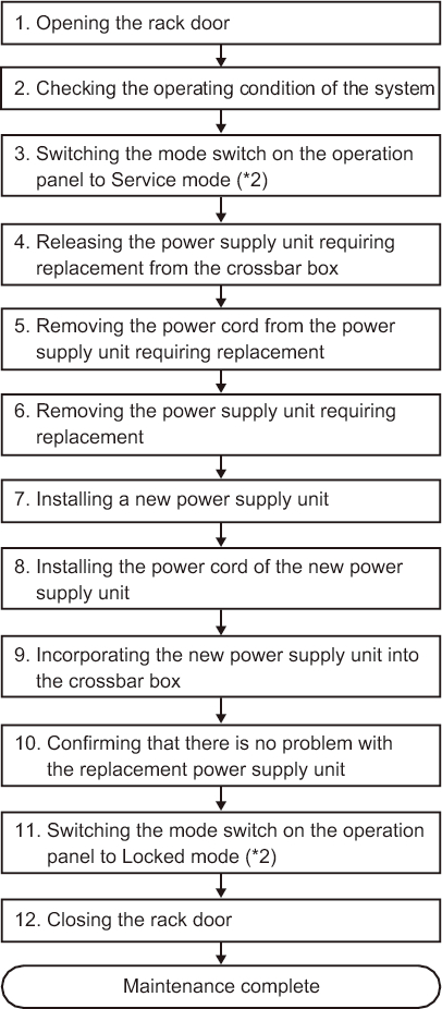
Active/Hot Replacement of the Power Supply Unit
Active/Hot replacement can be performed on the power supply unit. Perform the following procedure to replace it.
|
Figure 7-8 Flow of Active/Hot Replacement of the Power Supply Unit (*1)
|
|
*1 The same procedure is used for inactive/hot replacement of the power supply unit. *2 The mode switch on the operation panel does not need to be changed in active maintenance. |
| Item |
Work Procedure | Reference |
|---|---|---|
| 1 | Opening the rack door | |
| 2 | Checking the operating condition of the system | "4.1.1 Confirming the Hardware Configuration" |
| 3 | Switching the mode switch on the operation panel to Service mode (*2) | "5.2.2 Switching the Mode Switch to Service Mode" |
| 4 | Releasing the power supply unit requiring replacement from the crossbar box | "5.4.1 Releasing FRUs of the Crossbar Box With the replacefru Command" |
| 5 | Removing the power cord from the power supply unit requiring replacement | "5.5.1 Removing the Power Cord" |
| 6 | Removing the power supply unit requiring replacement | "13.3 Removing a Power Supply Unit" |
| 7 | Installing a new power supply unit | "13.4 Installing a Power Supply Unit" |
| 8 | Installing the power cord of a new power supply unit | "6.1.1 Installing the Power Cord" |
| 9 | Incorporating a new power supply unit into the crossbar box. | "6.2.1 Restoring the Crossbar Box With the replacefru Command" |
| 10 | Confirming that there is no problem with the replacement power supply unit | "6.3.2 Checking the FRU Status After Maintenance" |
| 11 | Switching the mode switch on the operation panel to Locked mode (*2) | "6.6 Returning the Mode Switch to Locked Mode" |
| 12 | Closing the rack door | |
| *1 The same procedure is used for inactive/hot replacement of the power supply unit. *2 The mode switch on the operation panel does not need to be changed in active maintenance. |
||
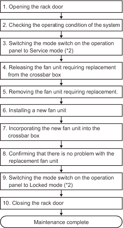
Active/Hot Replacement of the Fan Unit
Active/Hot replacement can be performed on the fan unit. Perform the following procedure to replace it.
|
Figure 7-9 Flow of Active/Hot Replacement of the Fan Unit (*1)
|
|
*1 The same procedure is used for inactive/hot replacement of the fan unit. *2 The mode switch on the operation panel does not need to be changed in active maintenance. |
| Item |
Work Procedure | Reference |
|---|---|---|
| 1 | Opening the rack door | |
| 2 | Checking the operating condition of the system | "4.1.1 Confirming the Hardware Configuration" |
| 3 | Switching the mode switch on the operation panel to Service mode (*2) | "5.2.2 Switching the Mode Switch to Service Mode" |
| 4 | Releasing the fan unit requiring replacement from the crossbar box | "5.4.1 Releasing FRUs of the Crossbar Box With the replacefru Command" |
| 5 | Removing the fan unit requiring replacement. | "15.3 Removing a Fan Unit" |
| 6 | Installing a new fan unit | "15.4 Installing a Fan Unit" |
| 7 | Incorporating the new fan unit into the crossbar box | "6.2.1 Restoring the Crossbar Box With the replacefru Command" |
| 8 | Confirming that there is no problem with the replacement fan unit | "6.3.2 Checking the FRU Status After Maintenance" |
| 9 | Switching the mode switch on the operation panel to Locked mode (*2) | "6.6 Returning the Mode Switch to Locked Mode" |
| 10 | Closing the rack door | |
| *1 The same procedure is used for inactive/hot replacement of the fan unit. *2 The mode switch on the operation panel does not need to be changed in active maintenance. |
||
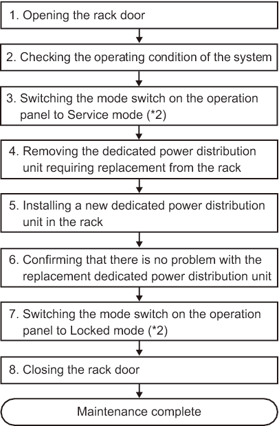
Active/Hot Replacement of the Dedicated Power Distribution Unit
Active/Hot replacement can be performed on the dedicated power distribution unit. Perform the following procedure to replace it.
|
Figure 7-10 Flow of Active/Hot Replacement of the Dedicated Power Distribution Unit (*1)
|
|
*1 The same procedure is used for inactive/hot replacement of the dedicated power distribution unit. *2 The mode switch on the operation panel does not need to be changed in active maintenance. |
| Item |
Work Procedure | Reference |
|---|---|---|
| 1 | Opening the rack door | |
| 2 | Checking the operating condition of the system | "4.1.1 Confirming the Hardware Configuration" |
| 3 | Switching the mode switch on the operation panel to Service mode (*2) | "5.2.2 Switching the Mode Switch to Service Mode" |
| 4 | Removing the dedicated power distribution unit requiring replacement from the rack. | "20.3 Removing the Dedicated Power Distribution Unit" |
| 5 | Installing a new dedicated power distribution unit in the rack | "20.4 Installing the Dedicated Power Distribution Unit" |
| 6 | Confirming that there is no problem with the replacement dedicated power distribution unit | "4.1.1 Confirming the Hardware Configuration" |
| 7 | Switching the mode switch on the operation panel to Locked mode (*2) | "6.6 Returning the Mode Switch to Locked Mode" |
| 8 | Closing the rack door | |
| *1 The same procedure is used for inactive/hot replacement of the dedicated power distribution unit. *2 The mode switch on the operation panel does not need to be changed in active maintenance. |
||
< Previous Page | Next Page >