7.3 Inactive Maintenance Flow
7.3 Inactive Maintenance Flow
This section describes the workflow for performing the inactive replacement of the XSCF BB control cable and the crossbar cable that connect the crossbar box to the SPARC M12-2S or the SPARC M10-4S.
| Note - Maintenance is not available in the inactive/cold state for the FRUs mounted on the crossbar box. During inactive maintenance, the physical partition to which a FRU requiring maintenance belongs is stopped, but other physical partitions may be operating. Therefore, only hot maintenance can be performed with the power cord of the crossbar box connected. |
| Note - The maintenance workflow and procedure for the following FRUs are the same as those for active maintenance even when the physical partition is in the inactive state. For inactive maintenance of these FRUs, see "7.2 Active Maintenance Flow." - XSCF unit - XSCF DUAL control cable - XSCF BB control cable (connecting crossbar boxes to each other) - Power supply unit - Fan unit - Dedicated power distribution unit mounted on the rack for expanded connection |
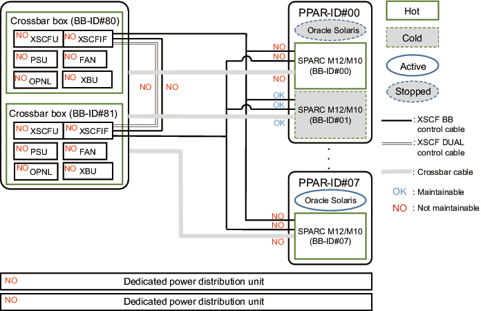
Figure 7-11 shows FRUs with inactive/cold maintenance enabled.
|
Figure 7-11 FRUs With Inactive/Cold Maintenance Enabled
|
|
Inactive/Cold maintenance has the following patterns:
Inactive/Cold Replacement of the XSCF BB Control Cable (Connecting the Crossbar Box to the SPARC M12-2S/M10-4S)
Inactive/Cold replacement can be performed on the XSCF BB control cable connecting the crossbar box to the SPARC M12-2S/M10-4S. Perform the following procedure to replace it.
|
Figure 7-12 Flow of Inactive/Cold Replacement of the XSCF BB Control Cable (Connecting the Crossbar Box to the SPARC M12-2S/M10-4S)
|
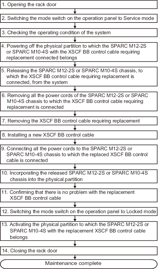 Flow of Inactive/Cold Replacement of the XSCF BB Control Cable (Connecting the Crossbar Box to the SPARC M12-2S/M10-4S)"/> Flow of Inactive/Cold Replacement of the XSCF BB Control Cable (Connecting the Crossbar Box to the SPARC M12-2S/M10-4S)"/>
|
| Item |
Work Procedure | Reference |
|---|---|---|
| 1 | Opening the rack door | |
| 2 | Switching the mode switch on the operation panel to Service mode | "5.2.2 Switching the Mode Switch to Service Mode" |
| 3 | Checking the operating condition of the system | "5.2.1 Checking the Operating Condition of the Physical Partition or Logical Domain" |
| 4 | Powering off the physical partition to which the SPARC M12-2S or SPARC M10-4S with the XSCF BB control cable requiring replacement connected belongs | "5.2.4 Powering Off a Connecting Physical Partition" |
| 5 | Releasing the SPARC M12-2S or SPARC M10-4S chassis, to which the XSCF BB control cable requiring replacement is connected, from the system | "5.4.2 Releasing FRUs in the Chassis of the Physical Partition" |
| 6 | Removing all the power cords of the SPARC M12-2S or SPARC M10-4S chassis to which the XSCF BB control cable requiring replacement is connected | "Removing the Power Cord of the SPARC M12-2S or the SPARC M10-4S" in "5.5.1 Removing the Power Cord" |
| 7 | Removing the XSCF BB control cable requiring replacement | "9.3 Removing an XSCF BB Control Cable" |
| 8 | Installing a new XSCF BB control cable | "9.4 Installing an XSCF BB Control Cable" |
| 9 | Connecting all the power cords to the SPARC M12-2S or SPARC M10-4S chassis to which the replaced XSCF BB control cable is connected | "Connecting the Power Cord to the SPARC M12-2S or the SPARC M10-4S" in "6.1.1 Installing the Power Cord" |
| 10 | Incorporating the released SPARC M12-2S or SPARC M10-4S chassis into the physical partition | "6.2.2 Restoring the FRUs of the Chassis of the Physical Partition" |
| 11 | Confirming that there is no problem with the replacement XSCF BB control cable | "6.3.2 Checking the FRU Status After Maintenance" |
| 12 | Switching the mode switch on the operation panel to Locked mode | "6.6 Returning the Mode Switch to Locked Mode" |
| 13 | Activating the physical partition to which the SPARC M12-2S or SPARC M10-4S with the replacement XSCF BB control cable belongs | "6.7 Powering On the Physical Partition Requiring Maintenance" |
| 14 | Closing the rack door |
Inactive/Cold Replacement of the Crossbar Cable
Inactive/Cold replacement can be performed on the crossbar cable. Perform the following procedure to replace it.
|
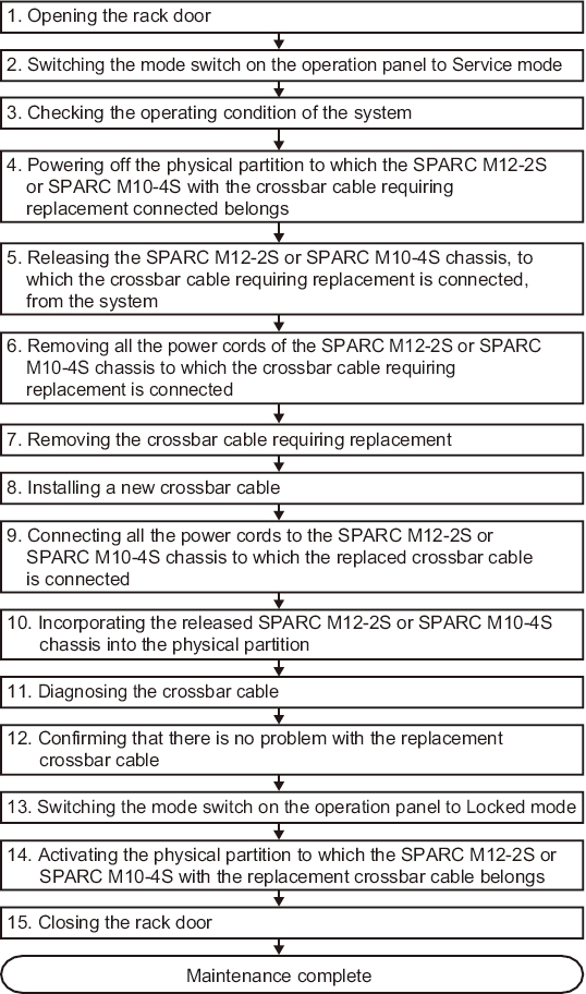
Figure 7-13 Flow of Inactive/Cold Replacement of the Crossbar Cable
|
|
| Item |
Work Procedure | Reference |
|---|---|---|
| 1 | Opening the rack door | |
| 2 | Switching the mode switch on the operation panel to Service mode | "5.2.2 Switching the Mode Switch to Service Mode" |
| 3 | Checking the operating condition of the system | "5.2.1 Checking the Operating Condition of the Physical Partition or Logical Domain" |
| 4 | Powering off the physical partition to which the SPARC M12-2S or SPARC M10-4S with the crossbar cable requiring replacement connected belongs | "5.2.4 Powering Off a Connecting Physical Partition" |
| 5 | Releasing the SPARC M12-2S or SPARC M10-4S chassis, to which the crossbar cable requiring replacement is connected, from the system | "5.4.2 Releasing FRUs in the Chassis of the Physical Partition" |
| 6 | Removing all the power cords of the SPARC M12-2S or SPARC M10-4S chassis to which the crossbar cable requiring replacement is connected | "Removing the Power Cord of the SPARC M12-2S or the SPARC M10-4S" in "5.5.1 Removing the Power Cord" |
| 7 | Removing the crossbar cable requiring replacement | "11.3 Removing a Crossbar Cable (Optical)" |
| 8 | Installing a new crossbar cable | "11.4 Installing a Crossbar Cable (Optical)" |
| 9 | Connecting all the power cords to the SPARC M12-2S or SPARC M10-4S chassis to which the replaced crossbar cable is connected | "Connecting the Power Cord to the SPARC M12-2S or the SPARC M10-4S" in "6.1.1 Installing the Power Cord" |
| 10 | Incorporating the released SPARC M12-2S or SPARC M10-4S chassis into the physical partition | "6.2.2 Restoring the FRUs of the Chassis of the Physical Partition" |
| 11 | Diagnosing the crossbar cable | "6.3.1 Diagnosing the Crossbar Unit and Crossbar Cables" |
| 12 | Confirming that there is no problem with the replacement crossbar cable | "6.3.2 Checking the FRU Status After Maintenance" |
| 13 | Switching the mode switch on the operation panel to Locked mode | "6.6 Returning the Mode Switch to Locked Mode" |
| 14 | Activating the physical partition to which the SPARC M12-2S or SPARC M10-4S with the replacement crossbar cable belongs | "6.7 Powering On the Physical Partition Requiring Maintenance" |
| 15 | Closing the rack door |
< Previous Page | Next Page >