18.4.2 Installing a Cable for the Connection Between the Terminal Board and Fan Backplane
18.4.2 Installing a Cable for the Connection Between the Terminal Board and Fan Backplane
Install the cable (SIG) or cable (PWR) connecting the terminal board and fan backplane.
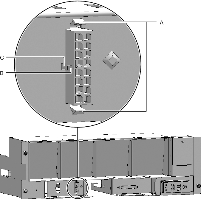
- Install the cable on the terminal board.- For the cable (PWR), install the connector that has latches (A in Figure 18-25) on both ends to the terminal board.
Install the tab (B in Figure 18-25) of the connector such that it fits in the notched section (C in Figure 18-25) of the terminal board.
|
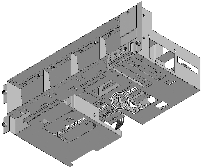
Figure 18-25 Installing the Cable (Cable (PWR))
|
|
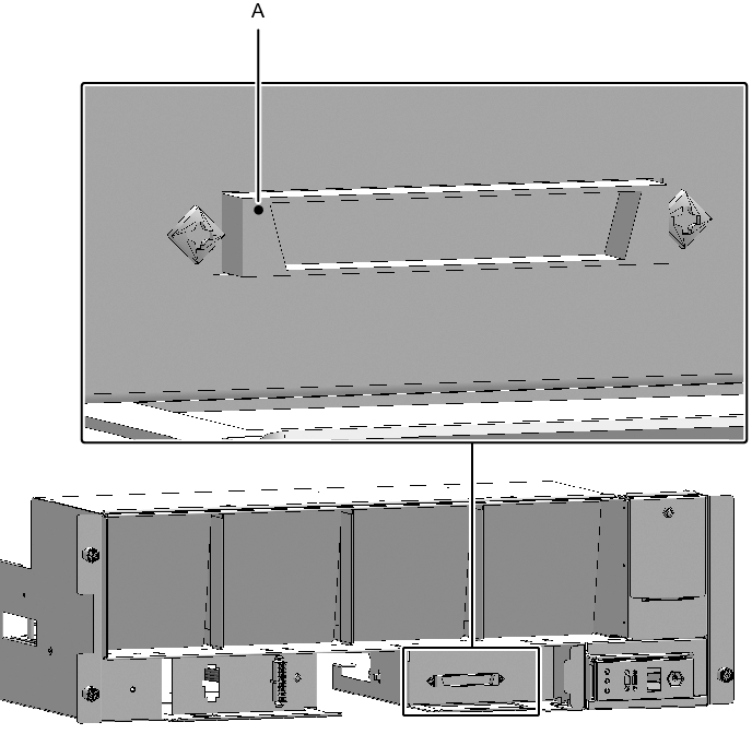
- ▪ For the cable (SIG), install the connector that has a threaded hole to the terminal board.
Use the screw that was removed from the same location. Tighten the screw with a Phillips screwdriver (bit No. 1). When installing the connector, orient the connector so that the dot indicated by A in Figure 18-26 is on the left.
|
Figure 18-26 Installing the Cable (Cable (SIG))
|
|
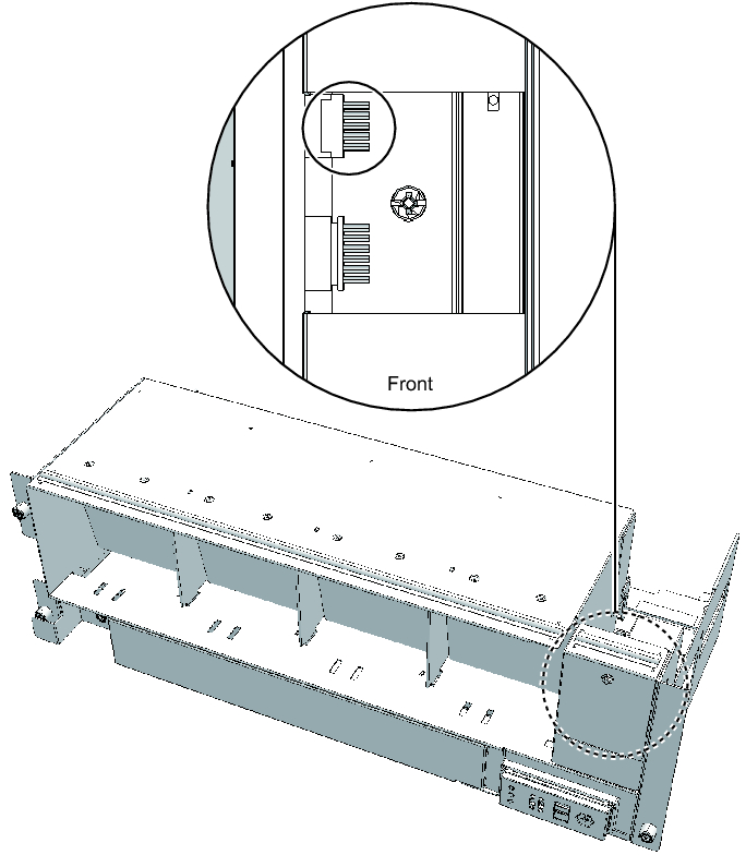
- Connect the cable to the connector of the fan backplane.
- Connect the cable connecting the fan shelf and operation panel to the connector on the operation panel.
Perform this step only when installing the cable (SIG).
To install the cable (PWR), proceed to step 4.
|
Figure 18-27 Operation Panel Cable
|
|
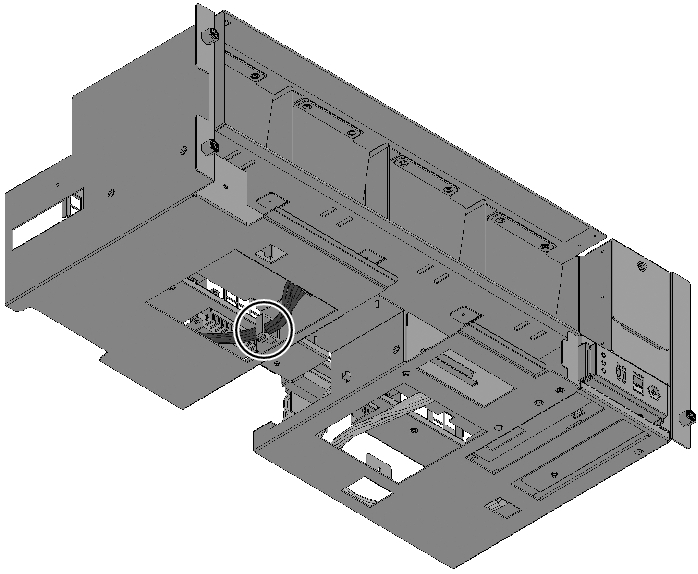
- Secure the cable with a clamp.
|
Figure 18-28 Securing the Cable (Cable (PWR))
|
|
|
Figure 18-29 Securing the Cable (Cable (SIG))
|
|
- Support the fan shelf from below with one hand, and carefully insert it into the chassis.
Arranging the cables in the center makes it easier to install the fan shelf. - Tighten the three screws securing the fan shelf.
- Connect the two cables to the fan shelf.
- Install the lower cover, and secure it with one screw.
- Install the upper cover.
- Slide the right and left stoppers of the upper cover outward, and secure the cover with two screws.
- Install all the fan units.
For details, see "15.4 Installing a Fan Unit." - Install the front cover.
For details, see "6.1.2 Installing the Front Cover."
The FRU installation work is completed. See "Chapter 7 Maintenance Flow" to continue maintenance work.
< Previous Page | Next Page >