2.2.2 Control Function of the Operation Panel
2.2.2 Control Function of the Operation Panel
The operation panel has the following switches to implement its control function:
- BB-ID switch
Identifies the crossbar box. - Mode switch (slide switch)
Specifies the operation or maintenance mode. - Power switch
Controls start/stop of the system.
|
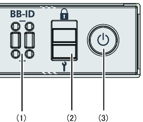
Figure 2-8 Operation Panel Switches
|
 "/> "/>
|
| Location Number | Switch |
|---|---|
| 1 | BB-ID switch |
| 2 | Mode switch |
| 3 | Power switch |
BB-ID switch
Use the BB-ID switch to set the BB-ID number of the crossbar box. Set #80 to #83 for the crossbar box. Table 2-3 describes how to operate the BB-ID switch.
| Operation | Description |
|---|---|
| Pressing the + side. | The BB-ID number increases by 1. |
| Pressing the - side | The BB-ID number decreases by 1. |
Mode switch (slide switch)
Use the mode switch to set the operation mode for the system. The Locked and Service operation modes can be switched by sliding the mode switch.
| Note - Set the same operation mode for both the crossbar box of the master XSCF and that of the standby XSCF. |
Table 2-4 describes the difference between the modes.
| Icon | Operation Mode | Description |
|---|---|---|

|
Locked mode | Mode used for normal operation - The power switch can be used to start the system but not to stop it. |

|
Service mode | Mode used for maintenance - The power switch cannot be used to start the system but can be used to stop it. - Place the system in Service mode to perform maintenance work with the system stopped. |
Table 2-5 describes the functions of the mode switch.
| Function | Mode Switch | |
|---|---|---|
| Locked | Service | |
| Starting/Stopping the system by the power switch | Only system startup is enabled. | A long press powers off the system. |
| Inhibition of break signal reception | Enabled. Using the setpparmode command, you can specify whether to receive break signals or inhibit their reception for each physical partition. | Disabled |
Power switch
Use the power switch to start or stop the system. The system starts/stops differently depending on how the power switch is pressed.
Table 2-6 describes how system starts/stops vary depending on how the power switch is pressed.
Table 2-6 describes how system starts/stops vary depending on how the power switch is pressed.
| Icon | Operation | Description | |
|---|---|---|---|

|
Brief press (From 1 second to less than 4 seconds) |
If the system has been started in Service mode (*1): | Operation is ignored. |
| If the system is stopped in Service mode: | Operation is ignored. | ||
| If the system has been started in Locked mode (*1): | Operation is ignored. | ||
| If the system is stopped in Locked mode: | Starts the system. If a wait time for air conditioning facilities or a warmup time is set on the XSCF, the process of waiting for the facilities to power on and for the warmup to complete is omitted at this time. |
||
| Long press (4 seconds or more) |
If the system has been started in Service mode (*1): | Perform the system shutdown process to stop the system. | |
| If the system startup process is in progress in Service mode: | Cancels the system startup process and stops the system. | ||
| If the system stop process is in progress in Service mode: | Continues the system stop process. | ||
| If the system is stopped in Service mode: | Operation is ignored. Even a long press does not start the system. |
||
| If the system is stopped in Locked mode: | Starts the system. If a wait time for air conditioning facilities or a warmup time is set on the XSCF, the process of waiting for the facilities to power on and for the warmup to complete is omitted. |
||
| If the system is not stopped in Locked mode: | Operation is ignored. | ||
| *1 If the system has been started, it means that at least one physical partition has been powered on. | |||
< Previous Page | Next Page >