11.4 Installing a Crossbar Cable (Optical)
11.4 Installing a Crossbar Cable (Optical)
This section describes the procedure for connecting the crossbar cables (optical).
- Attach the supplied connection destination label to the new replacement crossbar cable (optical).
For the new crossbar cable (optical), use the same type of label as the one on the cable requiring maintenance and write the same port numbers on it. - Connect a pair of crossbar cables (optical) to the chassis of the physical partition and the crossbar box.
Connect the crossbar cables to the locations of crossbar unit ports described on the label.
There are three types of crossbar cables (optical). Connect crossbar cables of the same type to the same port numbers.
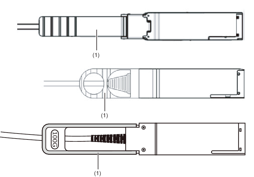
You can distinguish the type of crossbar cable by the tab shape. (See Figure 11-10.)
| Note - There is no problem if you connect the crossbar cables (optical) at the crossbar box while electricity is supplied. |
|

|
Figure 11-10 Crossbar Cable (Optical) Shapes and Tabs
|
|
| Number in Figure | Description |
|---|---|
| 1 | Tab |
Insert the crossbar cable (optical) by holding the connector part of the cable and inserting it straight into the opening. Do not hold the cable by the cable or tab part when inserting it.
|
| Note - Confirm that the crossbar cables (optical) are correctly connected and secure. |
| Note - After installing the crossbar cables (optical), use a hook-and-loop fastener to bundle the cables together and secure them to the rear cable support. |
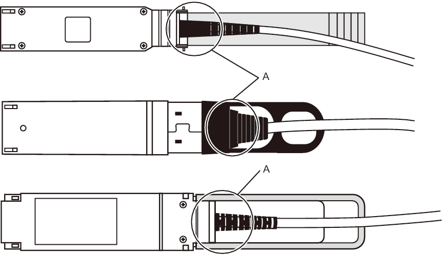
- Confirm that the crossbar cables are correctly and firmly connected.
With the crossbar cables connected to their ports, push in each cable while holding the joint (A in Figure 11-11) at the base of the crossbar cable connector.
|
|
Figure 11-11 Part to Hold When Checking a Crossbar Cable Connection
|
|
The FRU installation work is completed. See "Chapter 7 Maintenance Flow" to continue maintenance work.
< Previous Page | Next Page >