7.1 Maintenance Workflow
7.1 Maintenance Workflow
|
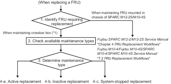
Figure 7-1 Maintenance Workflow in the Building Block Configuration With the Crossbar Box Connected
|
|
*1 This includes maintenance on cables connecting crossbar boxes to each other and cables connecting a crossbar box to the SPARC M12-2S/M10-4S. |
| Item | Procedure | Reference |
| 1 | Identifying the FRU to be replaced | "4.2.2 Identifying a Failure" |
| 2 | Checking the available maintenance types | "Table 7-2 Types of Maintenance That Can be Applied to Each Crossbar Box FRU" |
| 3 | Determining the maintenance types (*1) | |
| 4 | Replacing a FRU (*2) | |
| 4-a | Active replacement | "7.2 Active Maintenance Flow" |
| 4-b | Inactive replacement | "7.3 Inactive Maintenance Flow" |
| 4-c | System-stopped replacement | "7.4 System-Stopped Maintenance Flow" |
| *1 The configuration of the system requiring maintenance and the FRU to be replaced may affect system operation, such as in maintenance time and in stopping the logical domains. Consult with the system administrator to decide the maintenance type to be used. *2 FRUs mounted in the crossbar box can only be replaced, and no FRU can be added or removed. |
||
| Note - For systems in the building block configuration with the crossbar box connected, addition and removal work is enabled only for the target FRUs or the chassis of the physical partitions. To add or remove any FRU of a physical partition, see "Chapter 4 FRU Replacement Workflows" in the Fujitsu SPARC M12-2/M12-2S Service Manual or "Chapter 7 Maintenance Flow" in the Fujitsu M10-4/Fujitsu M10-4S/SPARC M10-4/SPARC M10-4S Service Manual. To add or remove the chassis of a physical partition, see Chapter 8 or subsequent parts in the Fujitsu SPARC M12-2S Installation Guide or Chapter 8 or subsequent parts in the Fujitsu M10-4S/SPARC M10-4S Installation Guide. |
Table 7-2 lists types of maintenance that can be applied to each crossbar box FRU. Active maintenance and inactive maintenance are not enabled when the power is disconnected or not being supplied.
-: Maintenance cannot be performed. |
||||||
| FRU | Active | Inactive | System Stopped | |||
| Hot Maintenance | Cold Maintenance | Hot Maintenance | Cold Maintenance | Hot Maintenance | Cold Maintenance | |
| XSCF unit | OK (*1) | - | OK (*1) (*5) | - | OK (*1) | OK (*4) |
| XSCF BB control cable | OK (*2) | OK (*2) | OK (*2) | OK (*2) | OK (*2) | OK (*2) |
| XSCF DUAL control cable | OK | - | OK (*5) | - | OK | OK (*4) |
| Crossbar cable | - | - | - | OK (*2) | - | OK (*2) |
| Crossbar unit | - | - | - | - | - | OK (*4) |
| Power supply unit | OK (*3) | - | OK (*3) (*5) | - | OK (*3) | OK (*4) |
| XSCF interface unit | - | - | - | - | - | OK (*4) |
| Fan unit | OK (*3) | - | OK (*3) (*5) | - | OK (*3) | OK (*4) |
| Fan backplane | - | - | - | - | - | OK (*4) |
| Operation panel | - | - | - | - | - | OK (*4) |
| Cable kit | - | - | - | - | - | OK (*4) |
| Crossbar backplane unit | - | - | - | - | - | OK (*4) |
| Dedicated power distribution unit | OK (*3) | - | OK (*3) (*5) | - | OK (*3) | OK (*4) |
| *1 Maintenance is performed on the XSCF in the standby state or a slave XSCF. If the XSCF is operating as the master XSCF, switch it to standby. To replace only the XSCF unit, active/hot maintenance is recommended where the physical partition does not stop. *2 Hot maintenance is enabled for maintenance on an XSCF BB control cable connecting crossbar boxes to each other. To maintain an XSCF BB control cable or a crossbar cable that connects the crossbar box to the chassis of the physical partition, the connected chassis must be powered off. *3 Maintenance is supported only for a redundant configuration. *4 Perform system-stopped/cold maintenance after all the physical partitions are stopped and the power cords of all the chassis are disconnected. *5 If the physical partition is operating, active/hot maintenance can also be performed. |
||||||
< Previous Page | Next Page >