18.3.2 Removing the Cables for the Connection Between the Terminal Board and Fan Backplane
18.3.2 Removing the Cables for the Connection Between the Terminal Board and Fan Backplane
Remove the cable (SIG) or cable (PWR) connecting the terminal board and fan backplane.
- Remove the front cover.
For details, see "5.5.2 Removing the Front Cover." - Remove all the fan units.
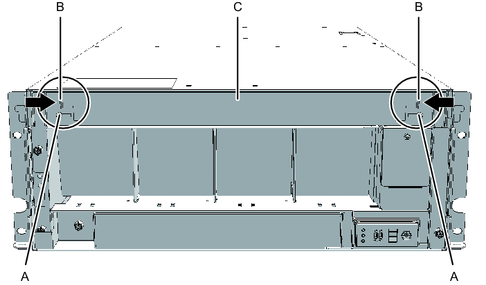
For details, see "15.3 Removing a Fan Unit." - Loosen the two screws (A in Figure 18-13) securing the upper cover, and slide the right and left stoppers (B in Figure 18-13) inward. Then, remove the upper cover (C in Figure 18-13).
|
Figure 18-13 Removing the Upper Cover
|
|
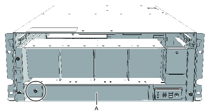
- Loosen the one screw (A in Figure 18-14) securing the lower cover, and slide the lower cover to the left to remove it.
|
Figure 18-14 Removing the Lower Cover
|
|
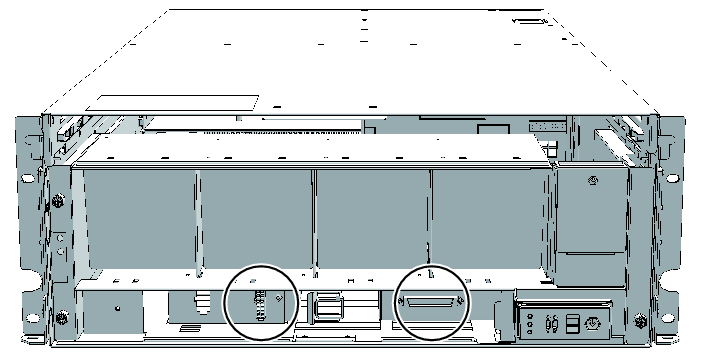
- Disconnect the two cables from the fan shelf.
Keep the disconnected cables together in the center of the shelf.
|
Figure 18-15 Removing the Cables
|
|
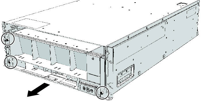
- Loosen the three screws securing the fan shelf and partially pull out the fan shelf.
|
Figure 18-16 Removing the Fan Shelf
|
|
- Place a hand under the fan shelf to support it, and carefully remove it from the chassis.
| Note - Remove the fan shelf while paying careful attention to the two cables arranged in the center. |
| Note - Place the removed fan shelf on a grounded antistatic ESD mat. |
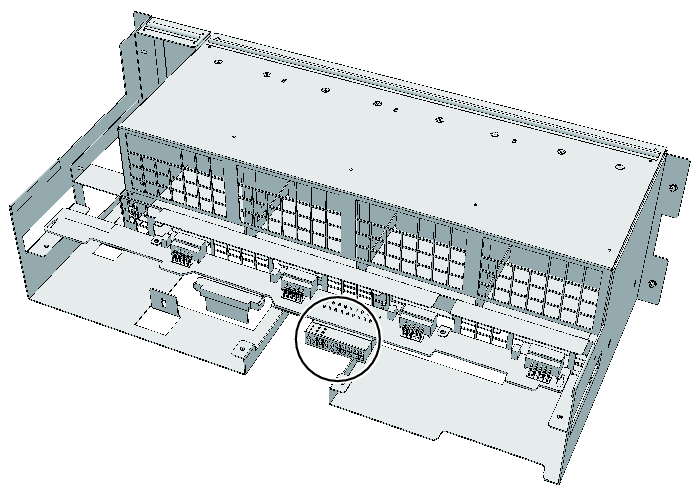
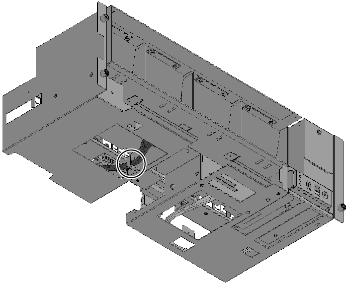
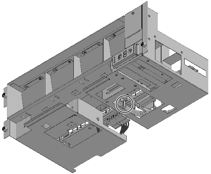
- Remove the cable connecting the fan backplane from the connector.
|
Figure 18-17 Removing the Cable (Cable (PWR))
|
|
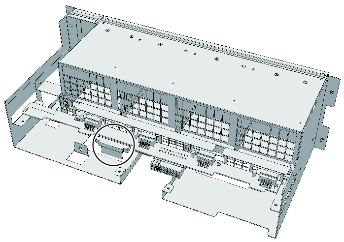
|
Figure 18-18 Removing the Cable (Cable (SIG))
|
|
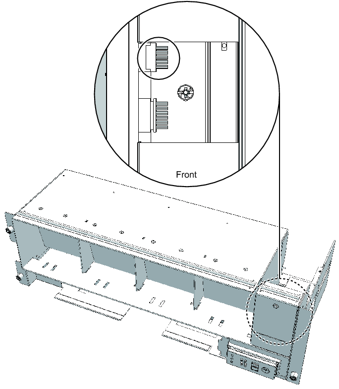
- Remove the cable connecting the fan shelf and operation panel from the connector on the operation panel.
Perform this step only when removing the cable (SIG).
To remove the cable (PWR), proceed to step 10.
|
Figure 18-19 Operation Panel Cable
|
|
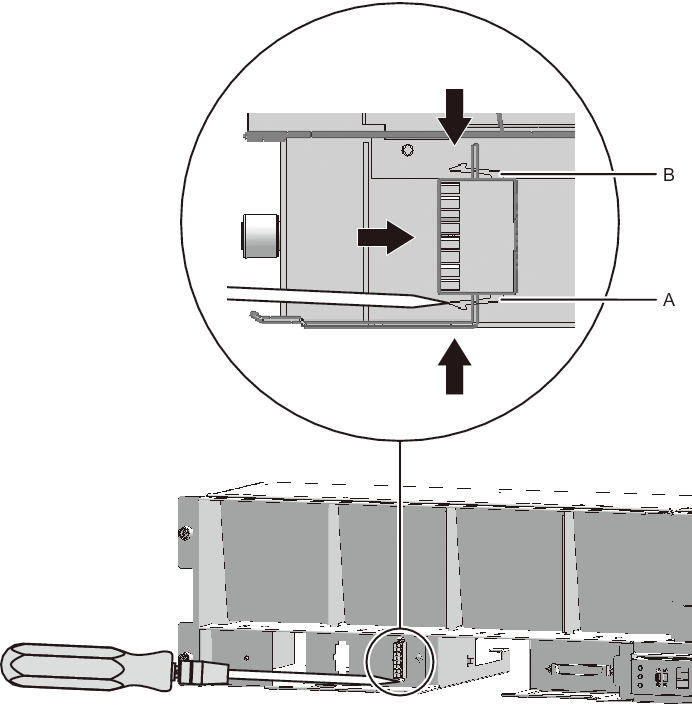
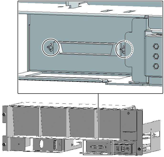
- Remove the cable from the terminal board.- For the cable (PWR), push the connector toward the back while pushing up the lower latch (A in Figure 18-20) with a flathead screwdriver. Confirm that the lower latch has been pushed to the back of the terminal board. Push the connector toward the back while pushing down the upper latch (B in Figure 18-20) with a flathead screwdriver.
|
Figure 18-20 Removing the Cable (Cable (PWR))
|
|
- ▪ For the cable (SIG), remove the two cable connector screws with a Phillips screwdriver (bit No. 1), and remove the cable from the terminal board.
|
Figure 18-21 Removing the Cable (Cable (SIG))
|
|
- Remove the cable from the clamps.
|
Figure 18-22 Removing the Cable (Cable (PWR))
|
|
|
Figure 18-23 Removing the Cable (Cable (SIG))
|
|
< Previous Page | Next Page >