2.2 Confirming the Functions of the Operation Panel
2.2 Confirming the Functions of the Operation Panel
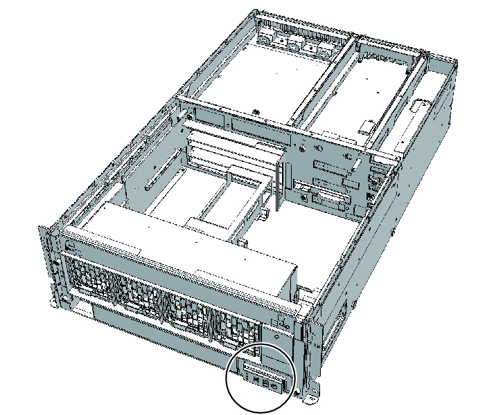
This section describes the functions of the operation panel mounted in the crossbar box.
The operation panel provides the system's display and control functions. The field engineer and system administrator can specify the operation mode or control start/stop of the system while checking the LEDs indicating the system operation status.
The operation panel provides the system's display and control functions. The field engineer and system administrator can specify the operation mode or control start/stop of the system while checking the LEDs indicating the system operation status.
|
Figure 2-5 Location of the Operation Panel
|
|
|
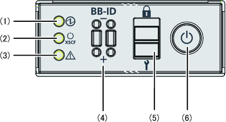
Figure 2-6 Appearance of the Operation Panel
|
|
| Location Number | LED/Switch |
|---|---|
| 1 | POWER LED |
| 2 | XSCF STANDBY LED |
| 3 | CHECK LED |
| 4 | BB-ID switch |
| 5 | Mode switch |
| 6 | Power switch |
The operation panel is mounted on each crossbar box chassis. However, only the operation panel on the chassis housing the master XSCF has all of its LEDs and switches enabled.
Table 2-2 shows the display and operation status of the operation panel.
Table 2-2 shows the display and operation status of the operation panel.
| LED/Switch on Operation Panel |
When Crossbar Box Acts as Master XSCF | When Crossbar Box Acts as XSCF Other Than Master XSCF |
|---|---|---|
| POWER LED | Enabled (Displays the start or stop status of the crossbar box) | Enabled (Displays the start or stop status of the crossbar box) |
| XSCF STANDBY LED |
Enabled (Displays the XSCF status of the system) | Enabled (Displays the XSCF status of the crossbar box) |
| CHECK LED | Enabled (Displays an abnormal status of the crossbar box) | Enabled (Displays an abnormal status of the crossbar box) |
| BB-ID switch | Enabled (Registers a BB-ID number) | Enabled (Registers a BB-ID number) |
| Mode switch (*1) | Enabled (Mode operation of the system) | Disabled |
| Power switch | Enabled (Start/stop operation of the system) | Disabled |
| *1 Set the same mode for the crossbar boxes with the master XSCF and XSCF in the standby state. If the settings are different, an asterisk (*) is displayed beside the components in the output of the showhardconf or showstatus command. | ||
< Previous Page | Next Page >