7.3.2 System-Stopped Addition
7.3.2 System-Stopped Addition
This section describes the workflows for system-stopped/hot and system-stopped/cold FRU addition. References to detailed descriptions are written in the workflow. See any of them as required.
System-stopped addition on the SPARC M12-1 has the following patterns:
System-stopped/hot addition (HDD/SSD)
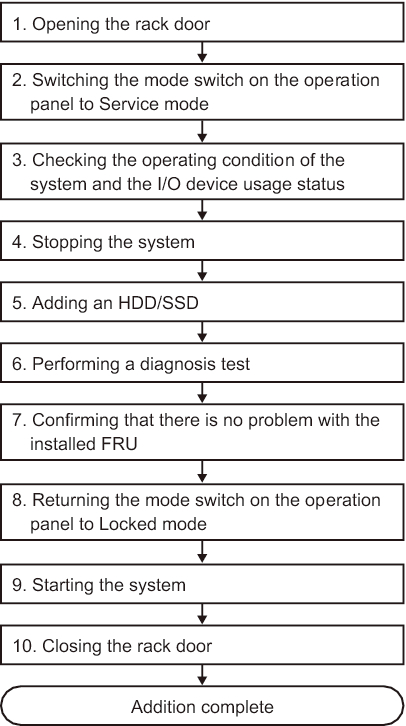
System-stopped/hot addition can be performed on an HDD/SSD. Perform the following procedure to add the unit.
|
Figure 7-8 System-Stopped/Hot Addition Flow (HDD/SSD)
|
|
| Item | Work Procedure | Reference |
|---|---|---|
| 1 | Opening the rack door | |
| 2 | Switching the mode switch on the operation panel to Service mode | "5.2 Switching the Mode Switch to Service Mode" |
| 3 | Checking the operating condition of the system and the I/O device usage status | "5.3 Checking the Operating Condition and Resource Usage Status" |
| 4 | Stopping the system | "5.5 Stopping the Entire System" |
| 5 | Adding an HDD/SSD | "Chapter 9 Maintaining Internal Storage" |
| 6 | Performing a diagnosis test | "6.4 Diagnosing a Replacement FRU" |
| 7 | Confirming that there is no problem with the added FRU | "6.7 Checking the FRU Status After Maintenance" |
| 8 | Returning the mode switch on the operation panel to Locked mode | "6.8 Returning the Mode Switch to Locked Mode" |
| 9 | Starting the system | "6.9 Starting the System" |
| 10 | Closing the rack door |
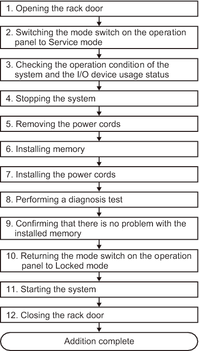
System-Stopped/Cold Addition (Memory)
System-stopped/cold addition can be performed on memory. Perform the following procedure to add the unit.
|
Figure 7-9 System-Stopped/Cold Addition Flow (Memory)
|
|
| Item | Work Procedure | Reference |
|---|---|---|
| 1 | Opening the rack door | |
| 2 | Switching the mode switch on the operation panel to Service mode | "5.2 Switching the Mode Switch to Service Mode" |
| 3 | Checking the operating condition of the system and the I/O device usage status | "5.3 Checking the Operating Condition and Resource Usage Status" |
| 4 | Stopping the system | "5.5 Stopping the Entire System" |
| 5 | Removing the power cords | "5.8.1 Removing the Power Cords" |
| 6 | Expanding memory | "16.5.1 Accessing the MBU" "16.6.2 Installing Memory" "16.6.3 Restoring the Server" |
| 7 | Installing the power cords | "6.1.6 Installing the Power Cords" |
| 8 | Performing a diagnosis test | "6.4 Diagnosing a Replacement FRU" |
| 9 | Confirming that there is no problem with the expanded memory | "6.7 Checking the FRU Status After Maintenance" |
| 10 | Returning the mode switch on the operation panel to Locked mode | "6.8 Returning the Mode Switch to Locked Mode" |
| 11 | Starting the system | "6.9 Starting the System" |
| 12 | Closing the rack door |
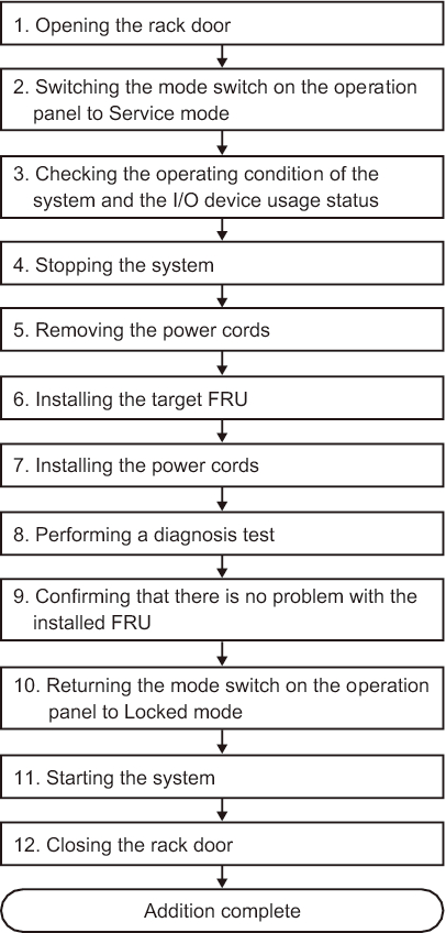
System-stopped/cold addition
System-stopped/cold addition can be performed on a PCIe card and HDD/SSD. Perform the following procedure to add the unit.
|
Figure 7-10 System-Stopped/Cold Addition Flow
|
|
| Item | Work Procedure | Reference |
|---|---|---|
| 1 | Opening the rack door | |
| 2 | Switching the mode switch on the operation panel to Service mode | "5.2 Switching the Mode Switch to Service Mode" |
| 3 | Checking the operating condition of the system and the I/O device usage status | "5.3 Checking the Operating Condition and Resource Usage Status" |
| 4 | Stopping the system | "5.5 Stopping the Entire System" |
| 5 | Removing the power cords | "5.8.1 Removing the Power Cords" |
| 6 | Adding the target FRU | When adding a PCIe card: "Chapter 8 Maintaining the PCI Express Cards" When adding an HDD/SSD: "Chapter 9 Maintaining Internal Storage" |
| 7 | Installing the power cords | "6.1.6 Installing the Power Cords" |
| 8 | Performing a diagnosis test | "6.4 Diagnosing a Replacement FRU" |
| 9 | Confirming that there is no problem with the added FRU | "6.7 Checking the FRU Status After Maintenance" |
| 10 | Returning the mode switch on the operation panel to Locked mode | "6.8 Returning the Mode Switch to Locked Mode" |
| 11 | Starting the system | "6.9 Starting the System" |
| 12 | Closing the rack door |
< Previous Page | Next Page >