2.1 Identifying the Names and Locations of Components
2.1 Identifying the Names and Locations of Components
This section describes the names and locations of the components mounted in the SPARC M12-1.
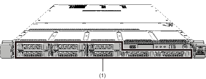
Components that can be accessed from the front
|
Figure 2-1 Locations of Components That Can be Accessed From the Front
|
|
| Location No. | Component |
|---|---|
| 1 | Internal storage (HDD/SSD) (*1) |
| *1 Represents both a hard disk drive (HDD) and solid state drive (SSD) unless otherwise noted. | |
Letters in parentheses are an abbreviation for the component. Below, each component is represented by its abbreviation unless otherwise noted.
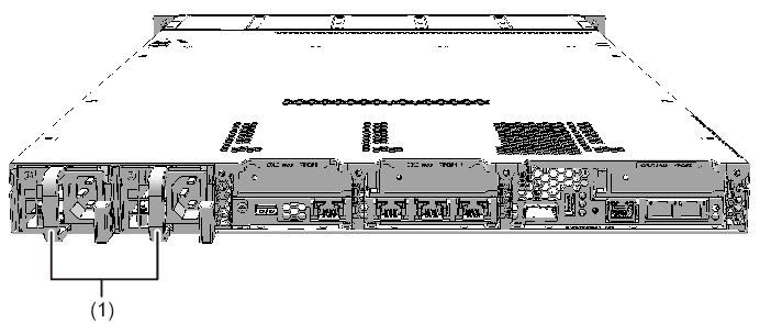
Components that can be accessed from the rear
|
Figure 2-2 Locations of Components That Can be Accessed From the Rear
|
|
| Location No. | Component |
|---|---|
| 1 | Power supply unit (PSU) |
Letters in parentheses are an abbreviation for the component. Below, each component is represented by its abbreviation unless otherwise noted.
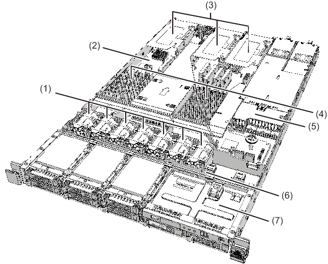
Internal components
To access the internal components, open the fan cover and remove the upper cover. For details on how to remove the covers, see "5.8.4 Opening the Fan Cover" or "5.8.5 Removing the Upper Cover."
|
Figure 2-3 Locations of Internal Components
|
|
| Location No. | Component |
|---|---|
| 1 | Fan unit (FANU) |
| 2 | Motherboard unit (MBU) |
| 3 | PCI Express card (PCIe card) |
| 4 | Memory (MEM) |
| 5 | PSU backplane (PSUBP) |
| 6 | HDD backplane (HDDBP) |
| 7 | Operation panel (OPNL) |
Letters in parentheses are an abbreviation for the component. Below, each component is represented by its abbreviation unless otherwise noted.
< Previous Page | Next Page >