7.2.2 System-Stopped Replacement
7.2.2 System-Stopped Replacement
This section describes the workflows for system-stopped/hot and system-stopped/cold FRU replacement. References to detailed descriptions are written in the workflow. See any of them as required.
| Note - If the XSCF startup mode is high-speed mode, hardware cannot be replaced using the replacefru command. Replace hardware by performing system-stopped/cold replacement. |
System-stopped replacement on the SPARC M12-1 has the following patterns:
System-stopped/hot replacement (PSU and FANU)
System-stopped/hot replacement can be performed on a PSU and FANU. Perform the following procedure to replace the unit.
|
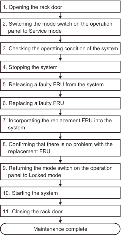
Figure 7-4 System-Stopped/Hot Replacement Flow (PSU and FANU)
|
|
| Item | Work Procedure | Reference |
|---|---|---|
| 1 | Opening the rack door | |
| 2 | Switching the mode switch on the operation panel to Service mode | "5.2 Switching the Mode Switch to Service Mode" |
| 3 | Checking the operating condition of the system | "5.3.1 Checking the Operating Condition of a Physical Partition or Logical Domain" |
| 4 | Stopping the system | "5.5 Stopping the Entire System" |
| 5 | Releasing a faulty FRU from the system | "5.7 Releasing a FRU From the System With the replacefru Command" |
| 6 | Replacing the faulty FRU | "Chapter 11 Maintaining the Power Supply Units" "Chapter 15 Maintaining the Fan Units" |
| 7 | Incorporating the replacement FRU into the system | "6.2 Incorporating a FRU Into the System With the replacefru Command" |
| 8 | Confirming that there is no problem with the replacement FRU | "6.7 Checking the FRU Status After Maintenance" |
| 9 | Returning the mode switch on the operation panel to Locked mode | "6.8 Returning the Mode Switch to Locked Mode" |
| 10 | Starting the system | "6.9 Starting the System" |
| 11 | Closing the rack door |
System-stopped/hot replacement (HDD/SSD)
System-stopped/hot replacement can be performed on an HDD/SSD. Perform the following procedure to replace the unit.
|
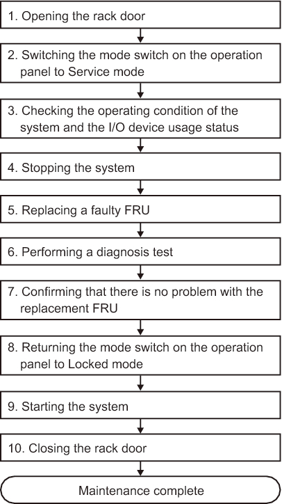
Figure 7-5 System-Stopped/Hot Replacement Flow (HDD/SSD)
|
|
| Item | Work Procedure | Reference |
|---|---|---|
| 1 | Opening the rack door | |
| 2 | Switching the mode switch on the operation panel to Service mode | "5.2 Switching the Mode Switch to Service Mode" |
| 3 | Checking the operating condition of the system and the I/O device usage status | "5.3 Checking the Operating Condition and Resource Usage Status" |
| 4 | Stopping the system | "5.5 Stopping the Entire System" |
| 5 | Replacing the faulty FRU | "Chapter 9 Maintaining Internal Storage" |
| 6 | Performing a diagnosis test | "6.4 Diagnosing a Replacement FRU" |
| 7 | Confirming that there is no problem with the replacement FRU | "6.7 Checking the FRU Status After Maintenance" |
| 8 | Returning the mode switch on the operation panel to Locked mode | "6.8 Returning the Mode Switch to Locked Mode" |
| 9 | Starting the system | "6.9 Starting the System" |
| 10 | Closing the rack door |
System-stopped/cold replacement
System-stopped/cold replacement can be performed on the following FRUs:
- PCIe card
- MBU
- Memory
- HDD/SSD
- FANU
- PSU
- PSUBP
- HDDBP
- OPNL
- Cable kit
Perform the following procedure to replace the unit.
|
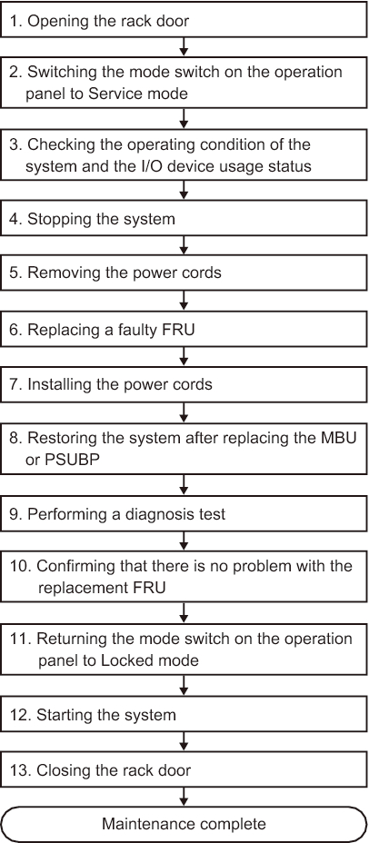
Figure 7-6 System-Stopped/Cold Replacement Flow
|
|
| Item | Work Procedure | Reference |
|---|---|---|
| 1 | Opening the rack door | |
| 2 | Switching the mode switch on the operation panel to Service mode | "5.2 Switching the Mode Switch to Service Mode" |
| 3 | Checking the operating condition of the system and the I/O device usage status | "5.3 Checking the Operating Condition and Resource Usage Status" |
| 4 | Stopping the system | "5.5 Stopping the Entire System" |
| 5 | Removing the power cords | "5.8.1 Removing the Power Cords" |
| 6 | Replacing the faulty FRU | See the maintenance procedure for each FRU. "Chapter 8 Maintaining the PCI Express Cards" "Chapter 9 Maintaining Internal Storage" "Chapter 10 Maintaining the HDD Backplane" "Chapter 11 Maintaining the Power Supply Units" "Chapter 12 Maintaining the PSU Backplane" (*1) "Chapter 13 Maintaining the Cable Kit" "Chapter 14 Maintaining the Operation Panel" "Chapter 15 Maintaining the Fan Units" "Chapter 16 Maintaining the Motherboard Unit/Memory" (*1)(*2) |
| 7 | Installing the power cords | "6.1.6 Installing the Power Cords" |
| 8 | Restoring the system after replacing the MBU or PSUBP | "6.3 When Replacing the MBU/PSUBP" (*3) |
| 9 | Performing a diagnosis test | "6.4 Diagnosing a Replacement FRU" |
| 10 | Confirming that there is no problem with the replacement FRU | "6.7 Checking the FRU Status After Maintenance" |
| 11 | Returning the mode switch on the operation panel to Locked mode | "6.8 Returning the Mode Switch to Locked Mode" |
| 12 | Starting the system | "6.9 Starting the System" |
| 13 | Closing the rack door | |
| *1 Simultaneous replacement of the MBU and PSUBP is prohibited. To replace the MBU and PSUBP, first replace either of the units and perform the work up to "10. Confirming that there is no problem with the replacement FRU." Then, return to "6. Replacing the faulty FRU," and replace the other unit. *2 If the motherboard unit is replaced in a system with internal storage used in a RAID volume configuration for a hardware RAID, you need to reactivate the hardware RAID volume before performing the work in "12. Starting the system." For details, see "14.2.11 Re-enabling a Hardware RAID Volume" in the Fujitsu SPARC M12 and Fujitsu M10/SPARC M10 System Operation and Administration Guide. *3 For details, see "Notes on Maintenance of a CPU Memory Unit, Motherboard Unit, XSCF Unit, PSU Backplane, or Crossbar Backplane Unit" in the Fujitsu SPARC M12 Product Notes for the latest XCP version. |
||
< Previous Page | Next Page >