7.4.2 System-stopped removal
7.4.2 System-stopped removal
This section describes the workflows for system-stopped/hot and system-stopped/cold FRU removal. References to detailed descriptions are written in the workflow. See any of them as required.
System-stopped removal on the SPARC M10-1 has the following patterns:
System-stopped/hot removal (for an internal disk)
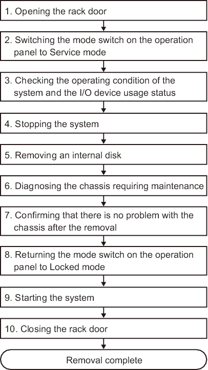
System-stopped/hot removal can be performed on an internal disk. Perform the following procedure to remove the unit.
|
Figure 7-12 System-stopped/hot removal flow (for an internal disk)
|
|
| Item | Work procedure | Reference |
|---|---|---|
| 1 | Opening the rack door | |
| 2 | Switching the mode switch on the operation panel to Service mode | "5.2 Switching the Mode Switch to Service Mode" |
| 3 | Checking the operating condition of the system and the I/O device usage status | "5.3 Checking the Operating Condition and Resource Usage Status" |
| 4 | Stopping the system | "5.5 Stopping the Entire System" |
| 5 | Removing an internal disk | "Chapter 9 Maintaining the Internal Disks" |
| 6 | Diagnosing the chassis requiring maintenance | "6.4 Diagnosing a Replacement FRU" |
| 7 | Confirming that there is no problem with the chassis after the removal | "6.7 Checking the FRU Status after Maintenance" |
| 8 | Returning the mode switch on the operation panel to Locked mode | "6.8 Returning the Mode Switch to Locked Mode" |
| 9 | Starting the system | "6.9 Starting the System" |
| 10 | Closing the rack door |
System-stopped/cold removal (for memory)
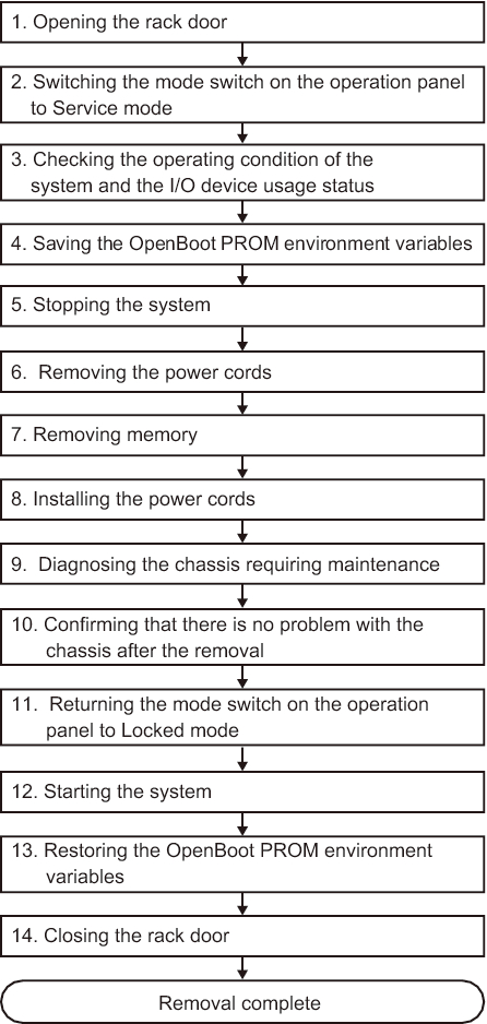
System-stopped/cold removal can be performed on memory. Perform removal according to the following procedure.
| Note - If the memory configuration is changed when a logical domain is used in a configuration other than factory-default, the system may start in the factory-default state of the logical domain configuration of the physical partition. In this case, the OpenBoot PROM environment variables of the control domain will be initialized too. To prepare for this possibility, record the configuration information for the OpenBoot PROM environment variables in the control domain before removing memory. After you remove memory, if the logical domain configuration of the physical partition enters the factory-default state, set the OpenBoot PROM environment variables and logical domain configuration again by referring to the recorded information. |
|
Figure 7-13 System-stopped/cold removal flow (for memory)
|
|
| Item | Work procedure | Reference |
|---|---|---|
| 1 | Opening the rack door | |
| 2 | Switching the mode switch on the operation panel to Service mode | "5.2 Switching the Mode Switch to Service Mode" |
| 3 | Checking the operating condition of the system and the I/O device usage status | "5.3 Checking the Operating Condition and Resource Usage Status" |
| 4 | Saving the OpenBoot PROM environment variables | "5.6.3 Saving the logical domain configuration information and OpenBoot PROM environment variables" |
| 5 | Stopping the system | "5.5 Stopping the Entire System" |
| 6 | Removing the power cords | "5.8.1 Removing the power cords" |
| 7 | Removing memory | "16.5.1 Accessing the motherboard unit" "16.5.2 Removing memory" "16.6.3 Restoring the chassis" |
| 8 | Installing the power cords | "6.1.6 Installing the power cords" |
| 9 | Diagnosing the chassis requiring maintenance | "6.4 Diagnosing a Replacement FRU" |
| 10 | Confirming that there is no problem with the chassis after the removal | "6.7 Checking the FRU Status after Maintenance" |
| 11 | Returning the mode switch on the operation panel to Locked mode | "6.8 Returning the Mode Switch to Locked Mode" |
| 12 | Starting the system | "6.9 Starting the System" |
| 13 | Restoring the OpenBoot PROM environment variables | "6.5.3 Restoring the logical domain configuration information and OpenBoot PROM environment variables" |
| 14 | Closing the rack door |
System-stopped/cold removal
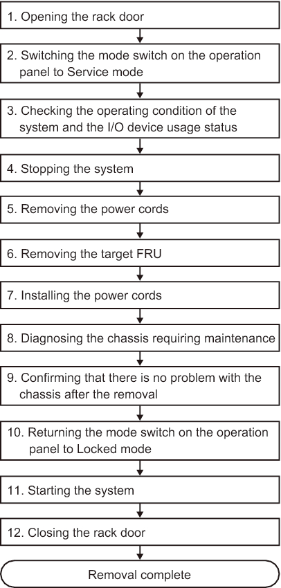
System-stopped/cold removal can be performed on a PCI Express card and an internal disk. Perform removal according to the following procedure.
|
Figure 7-14 System-stopped/cold removal flow
|
|
| Item | Work procedure | Reference |
|---|---|---|
| 1 | Opening the rack door | |
| 2 | Switching the mode switch on the operation panel to Service mode | "5.2 Switching the Mode Switch to Service Mode" |
| 3 | Checking the operating condition of the system and the I/O device usage status | "5.3 Checking the Operating Condition and Resource Usage Status" |
| 4 | Stopping the system | "5.5 Stopping the Entire System" |
| 5 | Removing the power cords | "5.8.1 Removing the power cords" |
| 6 | Removing the target FRU | When you remove a PCI Express card; "Chapter 8 Maintaining the PCI Express Cards" When you remove an internal disk; "Chapter 9 Maintaining the Internal Disks" |
| 7 | Installing the power cords | "6.1.6 Installing the power cords" |
| 8 | Diagnosing the chassis requiring maintenance | "6.4 Diagnosing a Replacement FRU" |
| 9 | Confirming that there is no problem with the chassis after the removal | "6.7 Checking the FRU Status after Maintenance" |
| 10 | Returning the mode switch on the operation panel to Locked mode | "6.8 Returning the Mode Switch to Locked Mode" |
| 11 | Starting the system | "6.9 Starting the System" |
| 12 | Closing the rack door |
< Previous Page | Next Page >