4.1 Connecting Cables to the SPARC M12-2
4.1 Connecting Cables to the SPARC M12-2
This section describes the procedure for connecting the serial cable, network cables, and power cords to the SPARC M12-2.
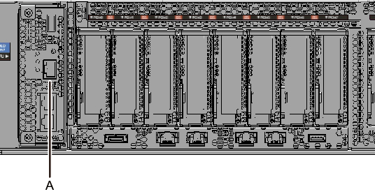
- Connect the serial cable supplied with the SPARC M12-2 from the serial port of the XSCF unit (A in Figure 4-1) to the system management terminal.
|
Figure 4-1 Serial Port Location
|
|
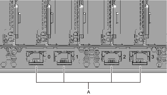
- Connect a LAN cable of Category 6 or higher from a 10 GbE LAN port (A in Figure 4-2) to the network switch or hub.
The 10 GbE LAN ports are used for the user network. Connect every other server, PC, UPS, etc. that is necessary for business via the network switch or hub.
| Note - The SPARC M12-2 (Fujitsu Product ID SPNBBAA3xx) onboard LAN (10 GbE LAN) cannot be used. You can see the Fujitsu Product ID (SPNxxxxxxx) on the front of the SPARC M12. |
|
Figure 4-2 10 GbE LAN Port Locations
|
|
- If a PCIe card is mounted, connect a LAN cable and I/O cable to the respective ports on the PCIe card.
- Secure the cables to the cable support.
While leaving extra length, secure the cables connected to the PCIe card to the cable support. - Attach a core to each supplied power cord, and connect the cord to a power supply unit.
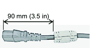
- a. Insert the power cord so that it fits into the groove of the core. Pinch the core closed until its latch is secured.
Attach the core at a location 90 mm (3.5 in) from the end of the power cord connector. (See Figure 4-3.)
|
Figure 4-3 Core attachment location
|
|
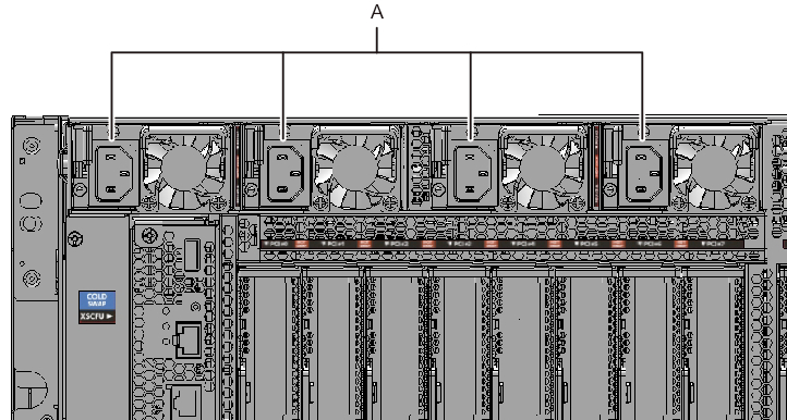
- b. Insert the power cord straight into the power supply unit (A in Figure 4-4) all the way.
Secure the power cords with cable clamps.
|
Figure 4-4 Power Supply Unit Locations
|
|
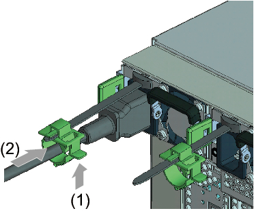
- Secure all the power cords with cable clamps.
Tighten the cable clamp until it holds the power cord tightly in place. ((1) in Figure 4-5)
Move the cable clamp to the base of the connector. ((2) in Figure 4-5)
|
Figure 4-5 Securing Power Cords
|
|
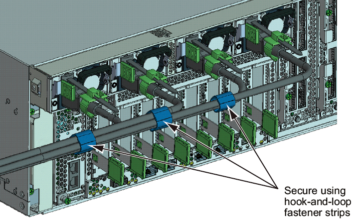
- While pulling the power cords toward the left side at the rear, gather them together, and bundle them with hook-and-loop fastener strips.
Ensure that the power cords do not hang in front of the PCIe cards under the power supply units.
|
Figure 4-6 Bundling Power Cords
|
|
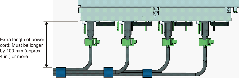
- Secure a sufficient extra length from the power supply unit to the bundling point of each power cord.
In order to perform active maintenance on the power supply unit, the power cord must have the extra length.
|
Figure 4-7 Securing the Extra Length for Power Cords
|
|
|
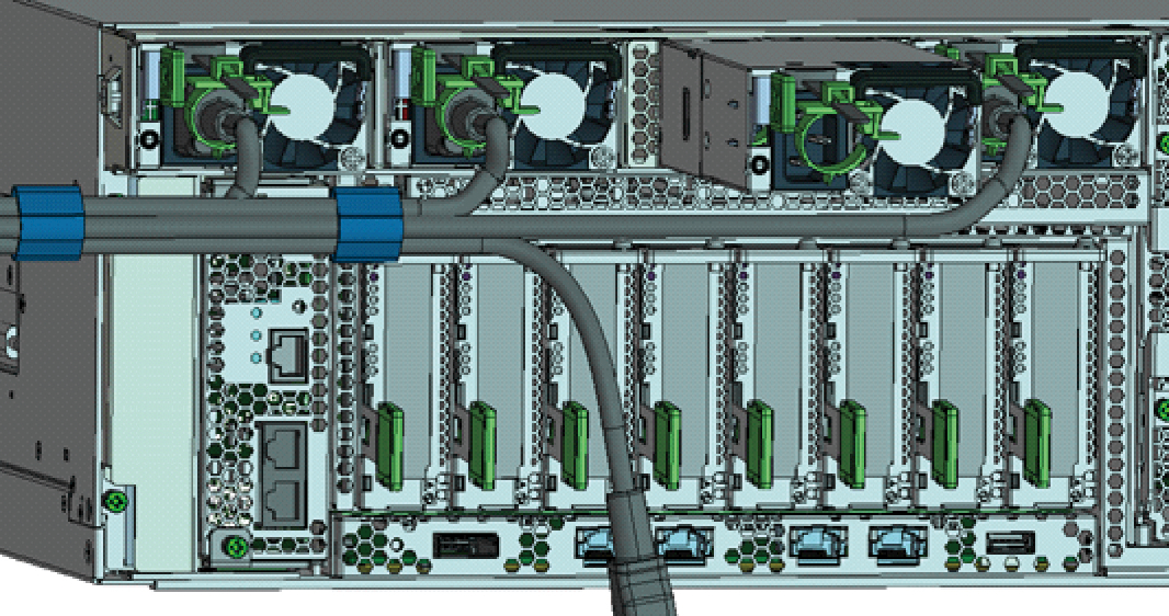
Figure 4-8 Reference: Example of Active Maintenance of a Power Supply Unit
|
|
| Note - Do not connect to an outlet at this point. |
< Previous Page | Next Page >