4.1 Connecting Cables to the SPARC M12-1
4.1 Connecting Cables to the SPARC M12-1
This section describes the procedure for connecting the serial cable, network cables, and power cords to the SPARC M12-1.
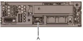
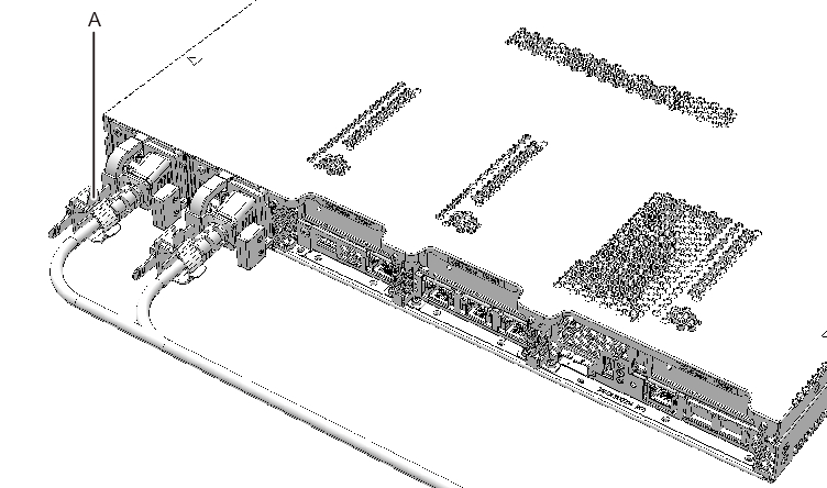
- Connect the serial cable supplied with the SPARC M12-1 from the serial port of the XSCF unit (A in Figure 4-1) to the system management terminal.
|
Figure 4-1 Serial Port Location on the XSCF Unit
|
|
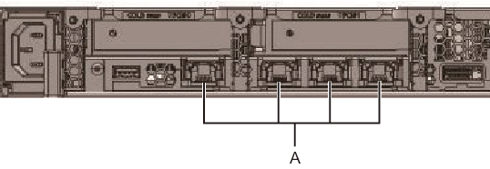
- Connect a LAN cable of Category 6 or higher from a 10 GbE LAN port (A in Figure 4-2) to the network switch or hub.
The 10 GbE LAN ports are used for the user network. Connect every other server, PC, UPS, etc. that is necessary for business via the network switch or hub.
| Note - The SPARC M12-1 (Fujitsu Product ID SPNAAAA3xx) onboard LAN (10 GbE LAN) cannot be used. You can see the Fujitsu Product ID (SPNxxxxxxx) on the front of the SPARC M12. |
|
Figure 4-2 10 GbE LAN Port Locations
|
|
- If a PCIe card is mounted, connect a LAN cable and I/O cable to the respective ports on the PCIe card.
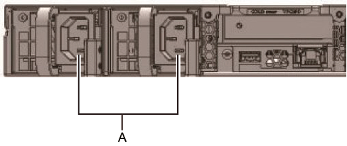
- Connect the supplied power cords to the power supply units (A in Figure 4-3).
Insert the power cords straight into the power supply units all the way.
|
Figure 4-3 Power Supply Unit Locations
|
|
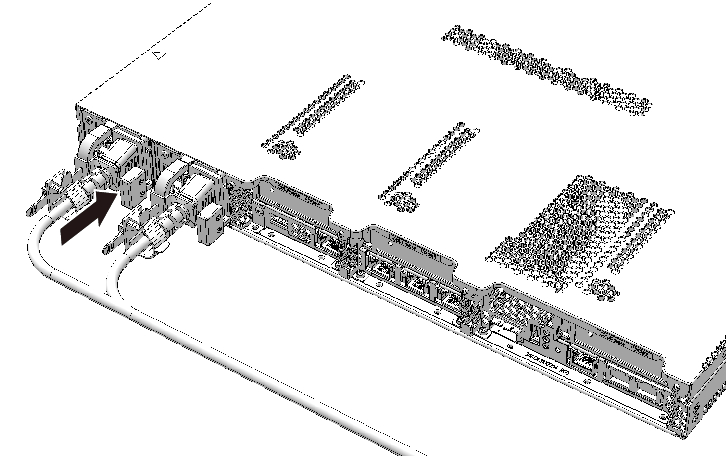
| Note - Do not connect to an outlet at this point. |
|
Figure 4-4 Attaching Power Cords
|
|
- Secure all the power cords with cable clamps.
Clip on the power cords to the cable clamps, and secure the cable clamps.
After locking each clasp (A in Figure 4-5), push the cable clamp toward the front of the chassis to firmly secure the clamp.
|
Figure 4-5 Locking a Cable Clamp
|
|
- Secure cables to the CMA.a. Pull out the chassis until the CMA is fully extended.b. Bundle cables such as the power cords, LAN cables, and FC cables, and secure them with the cable clamp on the CMA.c. Put the chassis back into the rack.
| Note - Ensure that the FC cable, when secured, has a bend radius of 30 mm (1.2 in.) or more. |
- Check the movement of the CMA.a. Pull out the chassis slowly to check whether it moves smoothly.b. Confirm that the laid cables are not twisted.
< Previous Page | Next Page >