3.4.1 Mounting the SPARC M12-1 in a Rack
3.4.1 Mounting the SPARC M12-1 in a Rack
This section describes the procedure for mounting the SPARC M12-1 in an equipment rack.
The procedure assumes the rack has supporting columns having square holes. The same procedure can be applied to the rack with supporting columns having M6 screw holes.
The procedure assumes the rack has supporting columns having square holes. The same procedure can be applied to the rack with supporting columns having M6 screw holes.
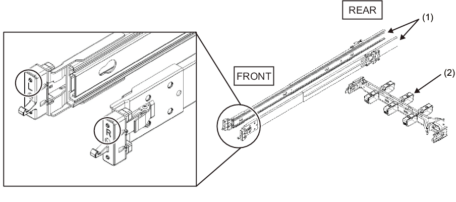
- Confirm that the rack rail kit supplied with the SPARC M12-1 is complete.
|
Figure 3-1 Rack Rail Kit
|
|
| Number in Figure | Name | Quantity |
| 1 | Slide rail (left/right) | 1 per side |
| 2 | Cable management arm | 1 |
- Confirm that the rack is secured in place to prevent the rack from toppling over.
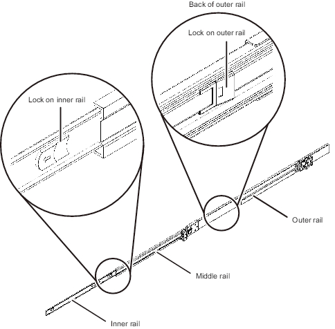
For details, see "3.3 Confirming the Rack." - Confirm the chassis mounting location in the rack.a. Confirm the mounting location in the rack. If necessary, mark the location on the supporting columns.b. Confirm that the chassis mounting location is the same on the front and rear columns.c. Remove the inner rail from the slide rail.
|
Figure 3-2 Slide Rail
|
|
- d. Pull out the inner rail by releasing the lock on the inner rail.
The inner rail is attached to the chassis in step 5.e. Release the lock on the middle rail, and store it in the outer rail.
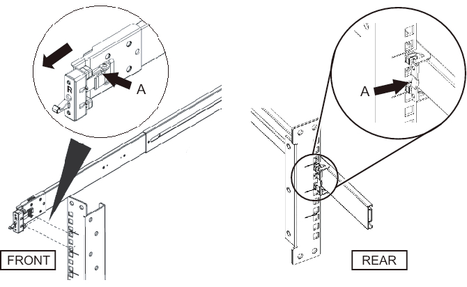
- Attach a slide rail to the rack.a. Confirm the attachment direction of the slide rail.
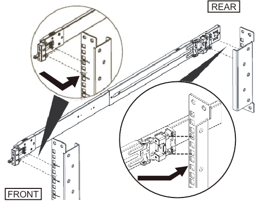
The [R] mark on the slide rail indicates the right side, and the [L] mark indicates the left side. The [FRONT] mark on the slide rail should be positioned at the front of the rack.b. From the front of the rack, attach the slide rail to the rear supporting column of the rack. (See Figure 3-3.)
At this time, attach the slide rail brackets to the supporting column of the rack, and align the protrusions on the slide rail with the holes in the supporting column (attachment locations). Then, push back the slide rail. (The latch clicks at this time.)c. Pull the slide rail until the front of the rail meets the front of the front supporting column of the rack. Align the protrusions on the slide rail with the holes in the supporting column (attachment locations). Then, push the slide rail to the rear of the rack until it clicks and locks.
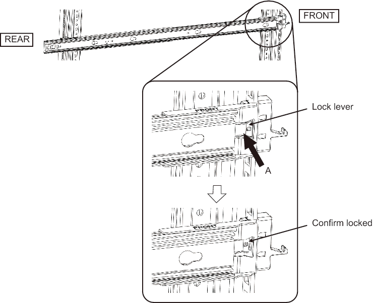
Push the lock lever (A in Figure 3-4) on the inside of rack rail, and confirm that the rail is locked.
Confirm that the attached slide rail is firmly locked by shaking it gently.d. Attach the slide rail on the other side in the same manner.
|
Figure 3-3 Attaching the Slide Rail
|
|
|
Figure 3-4 Confirming That the Slide Rail is Locked
|
|
| Remarks - To remove the slide rail, release the lock by pressing the part indicated by A in Figure 3-5, and pull the slide rail forward. |
|
Figure 3-5 Removing the Slide Rail
|
|
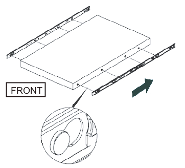
- Attach the inner rail removed in step 3 to the side of the chassis.
The left and right inner rails are the same.a. Align the insertion holes of the inner rail with the pins on the side of the chassis.b. Press and slide the inner rail toward the rear of the chassis.c. The latch clicks when the inner rail is secured to the chassis.d. Confirm that the attached inner rail is firmly locked and does not come loose by shaking it gently.e. Attach the inner rail on the other side in the same manner.
|
Figure 3-6 Attaching the Inner Rail
|
|
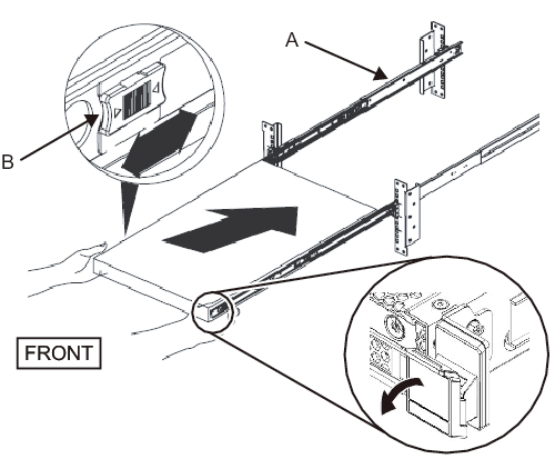
- Mount the chassis in the rack.a. Align the edge of the inner rail attached to the chassis with the edge of the middle rail on the rack (A in Figure 3-7), and insert the chassis.b. While you insert the chassis, the rail will click when locked. Move the green lock lever (B in Figure 3-7) on the inner rail forward to release the lock, and insert the chassis into the rack.
Fold out the green levers on the side edges of the front of the chassis, and push the chassis farther, all the way in. Then, release the levers to lock the chassis.c. Confirm that the chassis is secured to the rack by gently shaking the chassis.
|
Figure 3-7 Mounting the Chassis in the Rack
|
|
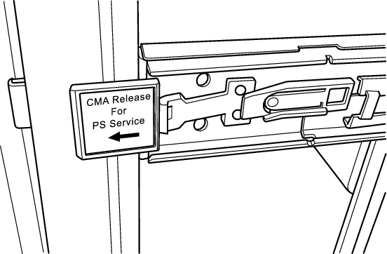
- Attach the cable management arm (referred to below as CMA).
The work of attaching the CMA is as viewed from the rear of the rack.a. Slide to remove the bracket marked "CMA Release For ..." from the CMA, and insert it into the slide rail along the grooves on the left side of the chassis.
|
Figure 3-8 Attaching the Bracket
|
|
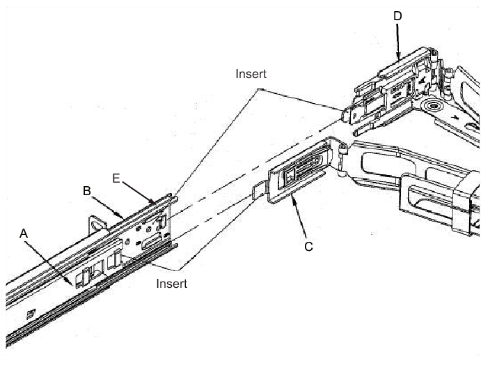
- b. Insert the smaller bracket (C in Figure 3-9) on the tip of the CMA into the right-edge clip portion (A in Figure 3-9) of the inner rail on the right side of the chassis.c. Insert the larger bracket (D in Figure 3-9) on the tip of the CMA into the right edge (B in Figure 3-9) of the slide rail on the right side of the chassis, along the guide groove (E in Figure 3-9).
|
Figure 3-9 Attaching the Right Side of the CMA
|
|
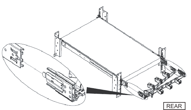
- d. While pushing out the green tag marked "CMA Release For ..." along the slide rail on the left side of the chassis, insert the tip of the left side of the CMA.e. Confirm that the CMA cannot be removed even when pulled forward. This completes the attachment process.
|
Figure 3-10 Attaching the Left Side of the CMA
|
|
|
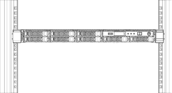
Figure 3-11 Completed SPARC M12-1 Configuration
|
|
< Previous Page | Next Page >