3.1.2 System That is Configured with a Host Node and a Remote Power Distribution Unit
3.1.2 System That is Configured with a Host Node and a Remote Power Distribution Unit
This section describes how to configure the remote power management by using a system that is configured with one SPARC M10-4 and one remote power distribution unit as an example. The basic setting process is the same as written in "3.1.1 System That is Configured with a Host Node and an I/O Node."
- Collect necessary information for a management file and create the file.
Collect the IP address and MAC address of the device where the remote power management will be configured. Based on the collected information, create a management file in CSV format for each remote power management group. The line feed code is LF or CR+LF.
- The remote power distribution unit supports the remote power management using IPMI. By connecting to an I/O device that does not support the remote power management using the WAKE on LAN through the IPMI, the power-on and power-off actions between SPARC M12 or SPARC M10 and the device can be interlocked.
When connecting to an I/O device with multiple controllers, redundancy can be increased by connecting a remote power distribution unit to each controller. In this case, when setting the management file of a remote power management group, set multiple remote power distribution units as one I/O node.
- Up to eight I/O devices can be connected to one remote power distribution unit. When setting a remote power distribution unit to a remote power management group, set them as one I/O node in the management file regardless of how many I/O devices are connected to the remote power distribution unit.
Set "0x00 (IPMI)" for the Operation setting of the remote power distribution unit.
- At least one master host node must be configured. Set "0x00: Disable" or "0x01: Enable (On)" for the Linkage setting of a host node. The operation does not change if "0x00: Disable," "0x01: Enable (On)," "0x02: Enable (Off)," or "0x03: Enable (On + 0ff)" is set.
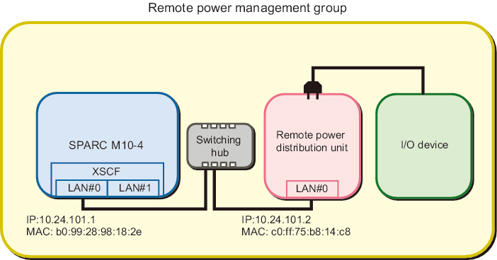
- In the following, how to configure the remote power management is described based on the configuration below.- Use only XSCF-LAN#0 of SPARC M10-4.- Use the system by connecting an I/O device to a remote power distribution unit.- Interlock the power-on and power-off actions of a remote power distribution unit.
- - Configure the settings as follows when using one I/O device connected to a remote power distribution unit.
|
Figure 3-6 System Using One I/O Device Connected to a Remote Power Distribution Unit
|
|
| Item | Setting Value | Remarks |
|---|---|---|
| GroupID | 1 | |
| NodeID | 1 | |
| NodeType | 0x01 | Master host node |
| NodeIdentName | 0123456789abcdef0000000000000001 | Unique ID that consists of a hexadecimal number with 32 digits, such as System GUID |
| Linkage | 0x01 | Interlocking power-on actions |
| Operation | 0x00 | IPMI |
| User | Blank | |
| Password | Blank | |
| IP0-0 | 10.24.101.1 | |
| Slave0-0 | 0x20 | Fixed value |
| MAC0-0 | b0:99:28:98:18:2e | |
| IP0-1 | Blank | |
| Slave0-1 | Blank | |
| MAC0-1 | Blank | |
| IP1-0 | Blank | |
| Slave1-0 | Blank | |
| MAC1-0 | Blank | |
| IP1-1 | Blank | |
| Slave1-1 | Blank | |
| MAC1-1 | Blank | |
| SubNode |
Blank |
| Item | Setting Value | Remarks |
|---|---|---|
| GroupID | 1 | |
| NodeID | 2 | |
| NodeType | 0x20 | Remote power distribution unit |
| NodeIdentName | 0123456789abcdef0000000000000002 | Unique ID that consists of a hexadecimal number with 32 digits, such as System GUID |
| Linkage | 0x03 | Interlocking power-on and power-off actions |
| Operation | 0x00 | IPMI |
| User | Blank | |
| Password | Blank | |
| IP0-0 | 10.24.101.2 | |
| Slave0-0 | 0x20 | Fixed value |
| MAC0-0 | c0:ff:75:b8:14:c8 | |
| IP0-1 | Blank | |
| Slave0-1 | Blank | |
| MAC0-1 | Blank | |
| IP1-0 | Blank | |
| Slave1-0 | Blank | |
| MAC1-0 | Blank | |
| IP1-1 | Blank | |
| Slave1-1 | Blank | |
| MAC1-1 | Blank | |
| SubNode | Blank |
- The management file is created as follows.
| 1,1,0x01,0123456789abcdef0000000000000001,0x01,0x00,,,10.24.101.1, 0x20,b0:99:28:98:18:2e,,,,,,,,,, 1,2,0x20,0123456789abcdef0000000000000002,0x03,0x00,,,10.24.101.2, 0x20,c0:ff:75:b8:14:c8,,,,,,,,,, |
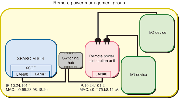
- - Even when multiple I/O devices are connected to a remote power distribution unit, configure the same settings as when using one I/O device connected to a remote power distribution unit. (See Figure 3-6.)
|
Figure 3-7 System in Which Multiple I/O Devices are Connected to a Remote Power Distribution Unit
|
|
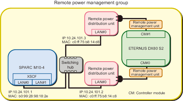
- - Set as follows when the multiple controllers of an I/O device in the system each connect to a remote power distribution unit.
|
Figure 3-8 System in Which the Multiple Controllers of an I/O Device Each Connect to a Remote Power Distribution Unit
|
|
| Note - If a model that is older than ETERNUS DXxx S2 is used with the firmware that was updated earlier than December 2012, an interlocking unit for power supply needs to be set between the ETERNUS and a remote power distribution unit. |
| Item | Setting Value | Remarks |
|---|---|---|
| GroupID | 1 | |
| NodeID | 2 | |
| NodeType | 0x20 | Remote power distribution unit |
| NodeIdentName | 0123456789abcdef0000000000000002 | Unique ID that consists of a hexadecimal number with 32 digits, such as System GUID |
| Linkage | 0x03 | Interlocking power-on and power-off actions |
| Operation | 0x00 | IPMI |
| User | Blank | |
| Password | Blank | |
| IP0-0 | 10.24.101.2 | |
| Slave0-0 | 0x20 | Fixed value |
| MAC0-0 | c0:ff:75:b8:14:c8 | |
| IP0-1 | Blank | |
| Slave0-1 | Blank | |
| MAC0-1 | Blank | |
| IP1-0 | Blank | |
| Slave1-0 | Blank | Fixed value |
| MAC1-0 | Blank | |
| IP1-1 | Blank | |
| Slave1-1 | Blank | |
| MAC1-1 | Blank | |
| SubNode |
Blank |
| Item | Setting Value | Remarks |
|---|---|---|
| GroupID | 1 | |
| NodeID | 3 | |
| NodeType | 0x20 | Remote power distribution unit |
| NodeIdentName | 0123456789abcdef0000000000000003 | Unique ID that consists of a hexadecimal number with 32 digits, such as System GUID |
| Linkage | 0x03 | Interlocking power-on and power-off actions |
| Operation | 0x00 | IPMI |
| User | Blank | |
| Password | Blank | |
| IP0-0 | 10.24.101.3 | |
| Slave0-0 | 0x20 | Fixed value |
| MAC0-0 | c0:ff:75:b8:14:d8 | |
| IP0-1 | Blank | |
| Slave0-1 | Blank | |
| MAC0-1 | Blank | |
| IP1-0 | Blank | |
| Slave1-0 | Blank | Fixed value |
| MAC1-0 | Blank | |
| IP1-1 | Blank | |
| Slave1-1 | Blank | |
| MAC1-1 | Blank | |
| SubNode |
Blank |
- The management file is created as follows.
| 1,1,0x01,0123456789abcdef0000000000000001,0x01,0x00,,,10.24.101.1, 0x20,b0:99:28:98:18:2e,,,,,,,,,, 1,2,0x20,0123456789abcdef0000000000000002,0x03,0x00,,,10.24.101.2, 0x20,c0:ff:75:b8:14:c8,,,,,,,,,, 1,3,0x20,0123456789abcdef0000000000000003,0x03,0x00,,,10.24.101.3, 0x20,c0:ff:75:b8:14:d8,,,,,,,,,, |
- Enable the IPMI service that is to be used for the remote power management function.Execute it by logging into the XSCF shell of all the host nodes and master host nodes where the remote power management is configured.
| XSCF> setpacketfilters -c ipmi_port enable |
- Configure a remote power management group using the created management file.a. Execute the showremotepwrmgmt command to confirm that the remote power management is not configured.Check the above by logging into the XSCF shell of all the host nodes and master host nodes where the remote power management is configured. When configuring the remote power management for the first time, it is normally assumed that the remote power management is not set.
- In the following example, the remote power management is not set.
| XSCF> showremotepwrmgmt -a Remote power management group is not configured. |
- If the existing settings for the remote power management are valid, initialize the settings according to the following process.
| XSCF> clearremotepwrmgmt -a All remote power management group informations are cleared.Continue? [y|n]: y |
- b. Execute the setremotepwrmgmt command to set a remote power management group.Execute this step by logging into the XSCF shell of the master host node in the remote power management group.
- Specify the management file created in step 1 and configure a remote power management group.
- Execute the following steps to download the management file of the remote power management group to a USB memory stick.1) Insert a USB memory stick into the USB port, on which "MAINTENANCE ONLY" is printed, on the back panel of the XSCF unit.The USB memory stick must be FAT32 format.The management file can be downloaded by using a USB memory stick or by specifying an http, https, or ftp server.2) Execute the setremotepwrmgmt command to set a remote power management group.If the settings of the downloaded management file are correct, enter "y" for "Continue? [y|n]:" to apply them.
| XSCF> setremotepwrmgmt -c config file:///media/usb_msd/path/rpmgroup-1.conf Mounted USB device Download successful: 29184Byte at 1016.857KB/s Checking file... The following Remote Power Management Group setting will be applied: GroupID :01 NodeID NodeType NodeIdentName PowerLinkage Operation ------ ----------- -------------------------------- ---------------------- ----------- 001 Master HOST 0123456789abcdef0000000000000001 Enable(Power-On Link) IPMI 002 PwrLinkBox 0123456789abcdef0000000000000002 Enable IPMI 003 PwrLinkBox 0123456789abcdef0000000000000003 Enable IPMI ------ ----------- -------------------------------- ---------------------- ----------- Continue? [y|n]: y The command completed successfully. XSCF> |
- Execute the setremotepwrmgmt command to enable the remote power management function.Execute this step for all host nodes and master host nodes where the remote power management is set.
| XSCF> setremotepwrmgmt -c enable Remote power management is enabled. Continue? [y|n]: y The command completed successfully. |
- Current setting details can be checked with the showremotepwrmgmt command.
| XSCF> showremotepwrmgmt [Remote Power Management Group#01 Information] Remote Power Management Status :[Enable] NodeID NodeType NodeIdentName Power PowerLinkage Operation ------ ----------- -------------------------------- ----- ---------------------- ----------- 001 Master HOST 0123456789abcdef0000000000000001 OFF Enable(Power-On Link) IPMI 002 PwrLinkBox 0123456789abcdef0000000000000002 OFF Enable IPMI 003 PwrLinkBox 0123456789abcdef0000000000000003 OFF Enable IPMI ------ ----------- -------------------------------- ----- ---------------------- ----------- |
< Previous Page | Next Page >