3.1.1 System That is Configured with a Host Node and an I/O Node
3.1.1 System That is Configured with a Host Node and an I/O Node
This section describes how to configure the remote power management by using a system that is configured with one SPARC M10-1 as a host node and one ETERNUS DX80 S2 as an I/O node as an example.
- Collect necessary information for a management file and create the file.
Collect the IP address and MAC address of the device where the remote power management will be configured. Based on the collected information, create a management file in CSV format for each remote power management group. The line feed code is LF or CR+LF.
- ETERNUS DX80 S2 supports multiple controllers. The system can be operated by setting a different or same IP address per controller. We recommend setting the same IP address. There are restrictions when a different IP address is set per controller. (See "Restrictions when a different IP address is set per controller.")
To operate the system with the same IP address set for multiple controllers, set the same IP address to IP0-0 and IP1-0 or IP0-1 and IP1-1. For details on how to check the ETERNUS controller configuration and IP addresses, see the ETERNUS manuals.
However, in either configuration, IP0-1 cannot be set without setting IP0-0. Similarly, IP1-1 cannot be set without setting IP1-0. Select IP0-0/IP0-1 or IP1-0/IP1-1 based on the LAN port of the SPARC M10 system to be connected and the type of controller used in the ETERNUS. For example, when connecting to LAN#0 of the XSCF, set the LAN of CM#0 to IP0-0 and the LAN of CM#1 to IP1-0. (See Figure 3-2.)
Restrictions when a different IP address is set per controller
- "IO Node power resumed" may be registered in the error log when an error occurs in the network and CM#0 cannot respond.
Furthermore, if the network is unstable, the "IO Node power resumed" error will be registered repeatedly.
The "IO Node power resumed" error usually indicates that an I/O node was powered on again since being powered off. However, if a different IP address is set per controller, the "IO Node power resumed" error may be registered even though no I/O node has been powered off. This issue is caused by the network.
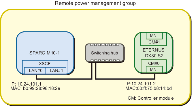
- - Configure the settings as follows when using only ETERNUS DX80 CM#0.
|
Figure 3-2 System Using Only ETERNUS DX80 CM#0
|
|
| Item | Setting Value | Remarks |
|---|---|---|
| GroupID | 1 | |
| NodeID | 1 | |
| NodeType | 0x01 | Master host node |
| NodeIdentName | 0123456789abcdef0000000000000001 | Unique ID that consists of a hexadecimal number with 32 digits, such as System GUID |
| Linkage | 0x01 | Interlocking power-on actions |
| Operation | 0x00 | IPMI |
| User | Blank | |
| Password | Blank | |
| IP0-0 | 10.24.101.1 | |
| Slave0-0 | 0x20 | Fixed value |
| MAC0-0 | b0:99:28:98:18:2e | |
| IP0-1 | Blank | |
| Slave0-1 | Blank | |
| MAC0-1 | Blank | |
| IP1-0 | Blank | |
| Slave1-0 | Blank | |
| MAC1-0 | Blank | |
| IP1-1 | Blank | |
| Slave1-1 | Blank | |
| MAC1-1 | Blank | |
| SubNode |
Blank |
| Item | Setting Value | Remarks |
|---|---|---|
| GroupID | 1 | |
| NodeID | 2 | |
| NodeType | 0x10 | I/O node |
| NodeIdentName | 0123456789abcdef0000000000000002 | Unique ID that consists of a hexadecimal number with 32 digits, such as System GUID |
| Linkage | 0x03 | Interlocking power-on and power-off actions |
| Operation | 0x01 | Wake On LAN |
| User | Blank | |
| Password | Blank | |
| IP0-0 | 10.24.101.2 | |
| Slave0-0 | 0x20 | Fixed value |
| MAC0-0 | 00:ff:75:b8:14:bd | |
| IP0-1 | Blank | |
| Slave0-1 | Blank | |
| MAC0-1 | Blank | |
| IP1-0 | Blank | |
| Slave1-0 | Blank | |
| MAC1-0 | Blank | |
| IP1-1 | Blank | |
| Slave1-1 | Blank | |
| MAC1-1 | Blank | |
| SubNode |
Blank |
- The management file is created as follows.
| 1,1,0x01,0123456789abcdef0000000000000001,0x01,0x00,,,10.24.101.1, 0x20,b0:99:28:98:18:2e,,,,,,,,,, 1,2,0x10,0123456789abcdef0000000000000002,0x03,0x01,,,10.24.101.2, 0x20,00:ff:75:b8:14:bd,,,,,,,,,, |
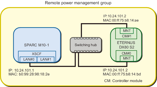
- - Configure the settings as follows when operating the system, setting the same IP address for multiple controllers using CM#0 and CM#1 of the ETERNUS DX80. (Recommended)
|
Figure 3-3 System in Which the Same IP Address is Specified for Multiple Controllers of the I/O Node
|
|
| Item | Setting Value | Remarks |
|---|---|---|
| GroupID | 1 | |
| NodeID | 2 | |
| NodeType | 0x10 | I/O node |
| NodeIdentName | 0123456789abcdef0000000000000002 | Unique ID that consists of a hexadecimal number with 32 digits, such as System GUID |
| Linkage | 0x03 | Interlocking power-on and power-off actions |
| Operation | 0x01 | Wake On LAN |
| User | Blank | |
| Password | Blank | |
| IP0-0 | 10.24.101.2 | |
| Slave0-0 | 0x20 | Fixed value |
| MAC0-0 | 00:ff:75:b8:14:bd | |
| IP0-1 | Blank | |
| Slave0-1 | Blank | |
| MAC0-1 | Blank | |
| IP1-0 | 10.24.101.2 | |
| Slave1-0 | 0x20 | Fixed value |
| MAC1-0 | 00:ff:75:b8:14:ae | |
| IP1-1 | Blank | |
| Slave1-1 | Blank | |
| MAC1-1 | Blank | |
| SubNode |
Blank | |
| *1 A colored line indicates that the setting is different from the original setting. | ||
- The management file is created as follows.
| 1,1,0x01,0123456789abcdef0000000000000001,0x01,0x00,,,10.24.101.1, 0x20,b0:99:28:98:18:2e,,,,,,,,,, 1,2,0x10,0123456789abcdef0000000000000002,0x03,0x01,,,10.24.101.2, 0x20,00:ff:75:b8:14:bd,,,,10.24.101.2,0x20,00:ff:75:b8:14:ae,,,, |
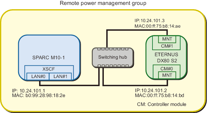
- - Configure as follows when operating the system by setting a different IP address for each controller using CM#0 and CM#1 of the ETERNUS DX80 S2. (Not recommended)
|
Figure 3-4 System in Which a Different IP Address are Specified for Multiple Controllers of I/O Nodes
|
|
| Item | Setting Value | Remarks |
|---|---|---|
| GroupID | 1 | |
| NodeID | 2 | |
| NodeType | 0x10 | I/O node |
| NodeIdentName | 0123456789abcdef0000000000000002 | Unique ID that consists of a hexadecimal number with 32 digits, such as System GUID |
| Linkage | 0x03 | Interlocking power-on and power-off actions |
| Operation | 0x01 | Wake On LAN |
| User | Blank | |
| Password | Blank | |
| IP0-0 | 10.24.101.2 | |
| Slave0-0 | 0x20 | Fixed value |
| MAC0-0 | 00:ff:75:b8:14:bd | |
| IP0-1 | Blank | |
| Slave0-1 | Blank | |
| MAC0-1 | Blank | |
| IP1-0 | 10.24.101.3 | |
| Slave1-0 | 0x20 | Fixed value |
| MAC1-0 | 00:ff:75:b8:14:ae | |
| IP1-1 | Blank | |
| Slave1-1 | Blank | |
| MAC1-1 | Blank | |
| SubNode |
Blank | |
| *1 A colored line indicates that the setting is different from the original setting. | ||
- The management file is created as follows.
| 1,1,0x01,0123456789abcdef0000000000000001,0x01,0x00,,,10.24.101.1, 0x20,b0:99:28:98:18:2e,,,,,,,,,, 1,2,0x10,0123456789abcdef0000000000000002,0x03,0x01,,,10.24.101.2, 0x20,00:ff:75:b8:14:bd,,,,10.24.101.3,0x20,00:ff:75:b8:14:ae,,,, |
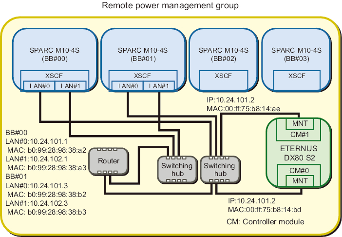
- - Configure as follows when using XSCF-LAN#0 and XSCF-LAN#1 in the 4BB configuration of the SPARC M10-4S.
XSCF-LAN#0 and XSCF-LAN#1 are connected to switches. Though the ETERNUS is connected with the same subnet as LAN#0, it is connected to LAN#1 of the SPARC M10-4S via a router.
|
Figure 3-5 System in Which XSCF-LAN#0 and XSCF-LAN#1 of SPARC M10-4S are Used
|
|
| Item | Setting Value | Remarks |
|---|---|---|
| GroupID | 1 | |
| NodeID | 1 | |
| NodeType | 0x01 | Master host node |
| NodeIdentName | 0123456789abcdef0000000000000001 | Unique ID that consists of a hexadecimal number with 32 digits, such as System GUID |
| Linkage | 0x01 | Interlocking power-on actions |
| Operation | 0x00 | IPMI |
| User | Blank | |
| Password | Blank | |
| IP0-0 | 10.24.101.1 | |
| Slave0-0 | 0x20 | Fixed value |
| MAC0-0 | b0:99:28:98:38:a2 | |
| IP0-1 | 10.24.102.1 | |
| Slave0-1 | 0x20 | Fixed value |
| MAC0-1 | b0:99:28:98:38:a3 | |
| IP1-0 | 10.24.101.3 | |
| Slave1-0 | 0x20 | Fixed value |
| MAC1-0 | b0:99:28:98:38:b2 | |
| IP1-1 | 10.24.102.3 | |
| Slave1-1 | 0x20 | Fixed value |
| MAC1-1 | b0:99:28:98:38:b3 | |
| SubNode |
Blank |
| Item | Setting Value | Remarks |
|---|---|---|
| GroupID | 1 | |
| NodeID | 2 | |
| NodeType | 0x10 | I/O node |
| NodeIdentName | 0123456789abcdef0000000000000002 | Unique ID that consists of a hexadecimal number with 32 digits, such as System GUID |
| Linkage | 0x03 | Interlocking power-on and power-off actions |
| Operation | 0x01 | Wake On LAN |
| User | Blank | |
| Password | Blank | |
| IP0-0 | 10.24.101.2 | |
| Slave0-0 | 0x20 | Fixed value |
| MAC0-0 | 00:ff:75:b8:14:bd | |
| IP0-1 | Blank | |
| Slave0-1 | Blank | |
| MAC0-1 | Blank | |
| IP1-0 | 10.24.101.2 | |
| Slave1-0 | 0x20 | Fixed value |
| MAC1-0 | 00:ff:75:b8:14:ae | |
| IP1-1 | Blank | |
| Slave1-1 | Blank | |
| MAC1-1 | Blank | |
| SubNode |
Blank | |
| *1 A colored line indicates that the setting is different from the original setting. | ||
- The management file is created as follows.
| 1,1,0x01,0123456789abcdef0000000000000001,0x01,0x00,,,10.24.101.1, 0x20,b0:99:28:98:38:a2,10.24.102.1,0x20,b0:99:28:98:38:a3,10.24.101.3,0x20,b0:99:28:98:38:b2,10.24.102.3,0x20,b0:99:28:98:38:b3, 1,2,0x10,0123456789abcdef0000000000000002,0x03,0x01,,,10.24.101.2, 0x20,00:ff:75:b8:14:bd,,,,10.24.101.2,0x20,00:ff:75:b8:14:ae,,,, |
- Enable the IPMI service that is to be used for the remote power management function.Execute it by logging into the XSCF shell of all the host nodes and master host nodes where the remote power management is configured.
| XSCF> setpacketfilters -c ipmi_port enable |
- Configure a remote power management group using the created management file.a. Execute the showremotepwrmgmt command to confirm that the remote power management is not configured.Check the above by logging into the XSCF shell of all the host nodes and master host nodes where the remote power management is configured. When configuring the remote power management for the first time, it is normally assumed that the remote power management is not set.
| XSCF> showremotepwrmgmt -a Remote power management group is not configured. |
- If the existing settings for the remote power management are valid, initialize the settings according to the following process.
| XSCF> clearremotepwrmgmt -a All remote power management group informations are cleared.Continue? [y|n]: y |
- b. Execute the setremotepwrmgmt command to set a remote power management group.Execute this step by logging into the XSCF shell of the master host node in the remote power management group.
- Specify the management file created in step 1 and configure a remote power management group.
- Execute the following steps to download the management file of the remote power management group to a USB memory stick.1) Insert a USB memory stick into the USB port, on which "MAINTENANCE ONLY" is printed, on the back panel of the XSCF unit.The USB memory stick must be FAT32 format.The management file can be downloaded by using a USB memory stick or by specifying an http, https, or ftp server.2) Execute the setremotepwrmgmt command to set a remote power management group.If the settings of the downloaded management file are correct, enter "y" for "Continue? [y|n]:" to apply them.
| XSCF> setremotepwrmgmt -c config file:///media/usb_msd/path/rpmgroup-1.conf Mounted USB device Download successful: 29184Byte at 1016.857KB/s Checking file... The following Remote Power Management Group setting will be applied: GroupID :01 NodeID NodeType NodeIdentName PowerLinkage Operation ------ ----------- -------------------------------- ---------------------- ----------- 001 Master HOST 0123456789abcdef0000000000000001 Enable(Power-On Link) IPMI 002 I/O 0123456789abcdef0000000000000002 Enable WakeUpOnLAN ------ ----------- -------------------------------- ---------------------- ----------- Continue? [y|n]: y The command completed successfully. XSCF> |
- Execute the setremotepwrmgmt command to enable the remote power management function.Execute this step for all host nodes and master host nodes where the remote power management is set.
| XSCF> setremotepwrmgmt -c enable Remote power management is enabled. Continue? [y|n]: y The command completed successfully. |
- Current setting details can be checked with the showremotepwrmgmt command.
| XSCF> showremotepwrmgmt [Remote Power Management Group#01 Information] Remote Power Management Status :[Enable] NodeID NodeType NodeIdentName Power PowerLinkage Operation ------ ----------- -------------------------------- ----- ---------------------- ----------- 001 Master HOST 0123456789abcdef0000000000000001 OFF Enable(Power-On Link) IPMI 002 I/O 0123456789abcdef0000000000000002 OFF Enable WakeUpOnLAN ------ ----------- -------------------------------- ----- ---------------------- ----------- |
< Previous Page | Next Page >