1.2 Understanding the Forms of Connection for Remote Power Management
1.2 Understanding the Forms of Connection for Remote Power Management
Connect through a LAN the host nodes, subnodes, and I/O nodes that support the remote power management function for SPARC M12 and SPARC M10.
The following table lists the connection specifications.
The following table lists the connection specifications.
| Item | Description |
|---|---|
| Forms of connection | LAN connection The connection takes either of the following forms: - Using XSCF-LAN#0 - Using XSCF-LAN#0 and XSCF-LAN#1 |
| Transmission speed | 100 Mbps or more |
| Internet protocol | IPv4 |
| DHCP | Unsupported If the remote power management function for SPARC M12 and SPARC M10 is used, you must set a fixed IP address for a connection target. |
| Connection protocol | IPMI (*1) over LAN (Intelligent Platform Management Interface) |
| *1 The supported IPMI version is IPMI 2.0. In SPARC M12 and SPARC M10, IPMI can be used only by the remote power management function. IPMI cannot be used by ipmitool or any function other than the remote power management function for SPARC M12 and SPARC M10. | |
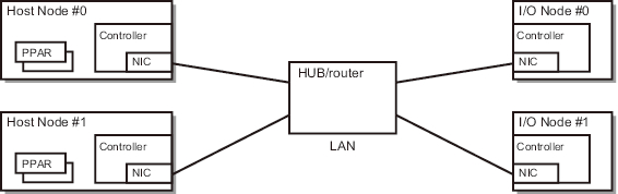
Standard connection for remote power management
Connect through an identical LAN the host nodes, subnodes, and I/O nodes that are equipped with a controller that supports the remote power management function for SPARC M12 and SPARC M10.
|
Figure 1-2 Standard Forms of Connection for Remote Power Management
|
|
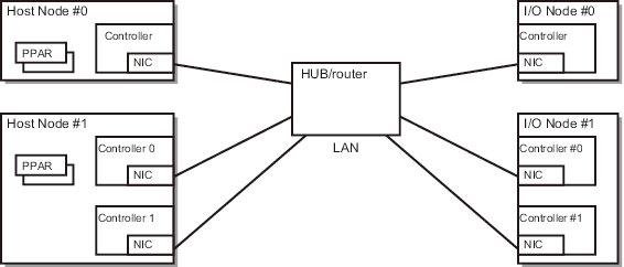
Connection when the controllers are duplicated
If the host node controllers are duplicated, each controller can be connected to the same LAN. Operation of the remote power management is performed from the master XSCF.
|
Figure 1-3 Forms of Connection for the Remote Power Management when the Controllers are Duplicated
|
|
| Note - For the I/O nodes that can be set as a takeover IP address between the controllers, we recommend setting a takeover IP address. In such cases, set controllers 0 and 1 to the same IP address in the management file for configuring a remote power management group. For details on specific settings, see "3.1.1 System That is Configured with a Host Node and an I/O Node." |
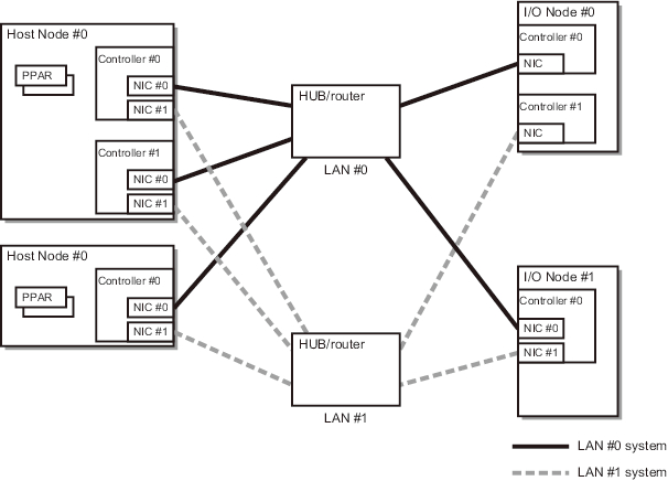
Connection when paths are duplicated
The paths of the remote power management connection can be duplicated under the following conditions.
- Two LAN cards can be mounted on the controllers of all nodes.
- Two LAN cards can be mounted on the controllers of the host nodes, and I/O nodes have either of the following configurations.- The controllers of the I/O nodes are duplicated.- Two LAN cards can be mounted on the controllers of the I/O nodes.
|
Figure 1-4 Forms of Connection for the Remote Power Management when Paths are Duplicated
|
|
< Previous Page | Next Page >