3.3 Relationship Between the CPU Configuration and Number of Root Complexes
3.3 Relationship Between the CPU Configuration and Number of Root Complexes
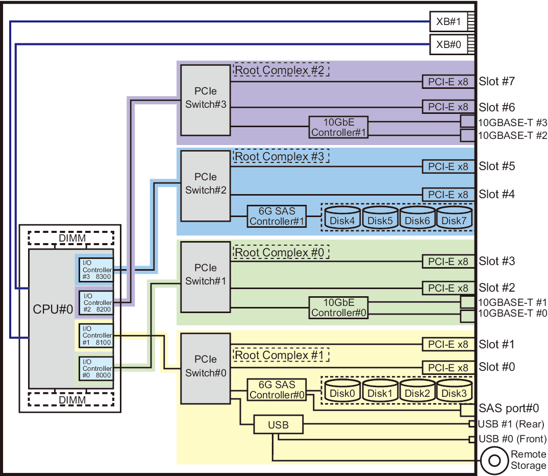
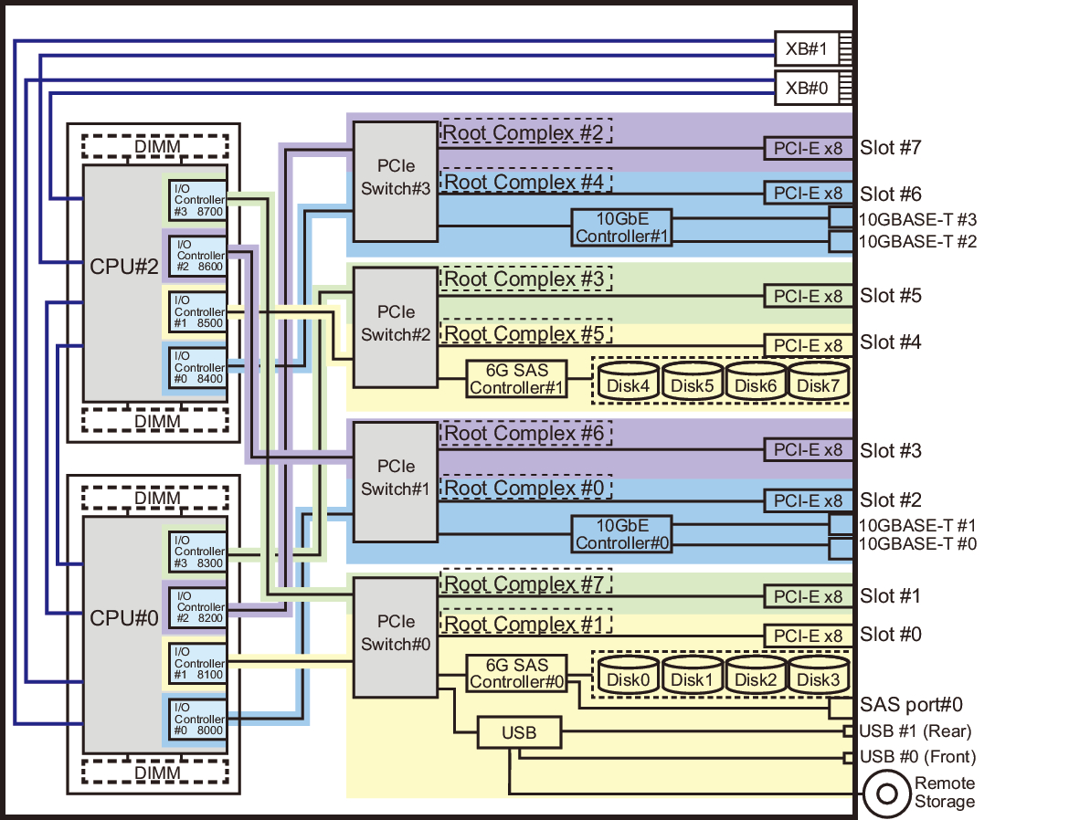
The 1-CPU configuration of the SPARC M12-2S consists of four root complexes, and the 2-CPU configuration consists of four or eight root complexes. A root complex consists of an I/O controller mounted on a processor and the PCI switches, PCI devices, etc. under the I/O controller.
The number of root complexes after on-site CPU module expansion has a default value of 4. It remains at this number by default. In this case, the system configuration can be kept as is since the I/O bus is not reconfigured. The PCI card mounting rules are also kept, so the same 1-CPU configuration rules apply.
To change the number of root complexes to eight, the system administrator needs to change the XSCF settings to reconfigure the I/O bus. For details on how to set the number, see the man page for the setpparmode(8) command or the Fujitsu SPARC M12 and Fujitsu M10/SPARC M10 XSCF Reference Manual. Changing the number of root complexes to eight increases the maximum number of mounted PCI cards. However, because device path names change with the reconfiguration of the I/O bus, system reconfiguration may be required for any device path name used by an application. An example of this reconfiguration is to set a device path name again.
| Ordered Only for Server | Ordered for CPU Module | |||
|---|---|---|---|---|
| Ordered Together With Server (Mounting at Factory) |
Ordered Separately From Server (Expansion on Site) | |||
| Without I/O Bus Reconfiguration | With I/O Bus Reconfiguration | |||
| Number of CPUs | 1 | 2 | 2 | 2 |
| Number of root complexes | 4 | 8 | 4 | 8 |
Figure 3-1 is a hardware configuration diagram of the SPARC M12-2S with 1 CPU. Figure 3-2 is a hardware configuration diagram of the SPARC M12-2S with 2 CPUs.
|
Figure 3-1 Hardware Configuration Diagram of the SPARC M12-2S With 1 CPU
|
|
|
Figure 3-2 Hardware Configuration Diagram of the SPARC M12-2S With 2 CPUs
|
|
< Previous Page | Next Page >