9.5.3 Removing the CPU memory unit upper
9.5.3 Removing the CPU memory unit upper
Remove the CPU memory unit upper after removing the CPU memory unit from the chassis. Perform reduction using the same procedure. For installation or for a system where the CPU memory unit upper is not mounted, remove the filler unit of the CPU memory unit upper.
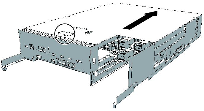
- Unlock (push) the top cover of the CPU memory unit, and remove the cover by sliding it in the direction of the arrow.
|
Figure 9-8 Releasing the lock
|
|
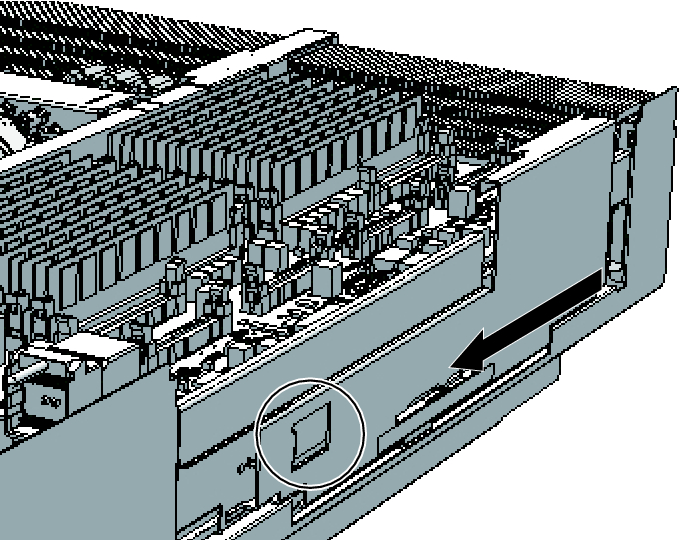
- Unlock (push) the right-side guide (when viewed from the rear) and remove it by sliding it in the direction of the arrow.
|
Figure 9-9 Removing right-side guide
|
|
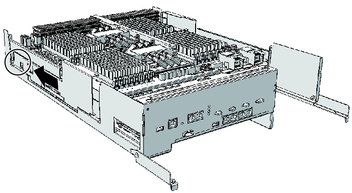
- Unlock (push) the left-side guide (when viewed from the rear) and remove it by sliding it in the direction of the arrow.
|
Figure 9-10 Removing left-side guide
|
|
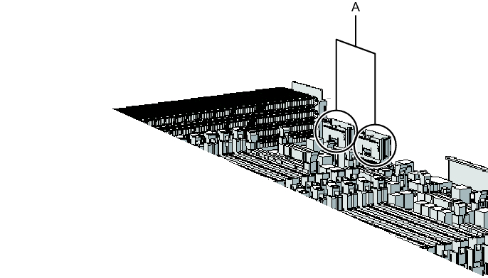
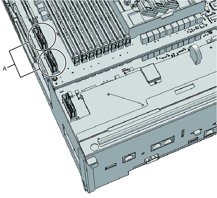
- Two PCIe cables (A in Figure 9-11) on the right side connect the CPU memory units upper and lower. Remove these cables from the CPU memory unit upper, and push them toward the outside of the chassis.
When removing the filler unit for the CPU memory unit upper, you do not need to remove the PCIe cables. Proceed to step 10.
|
Figure 9-11 Removing the right-side PCIe cables
|
|
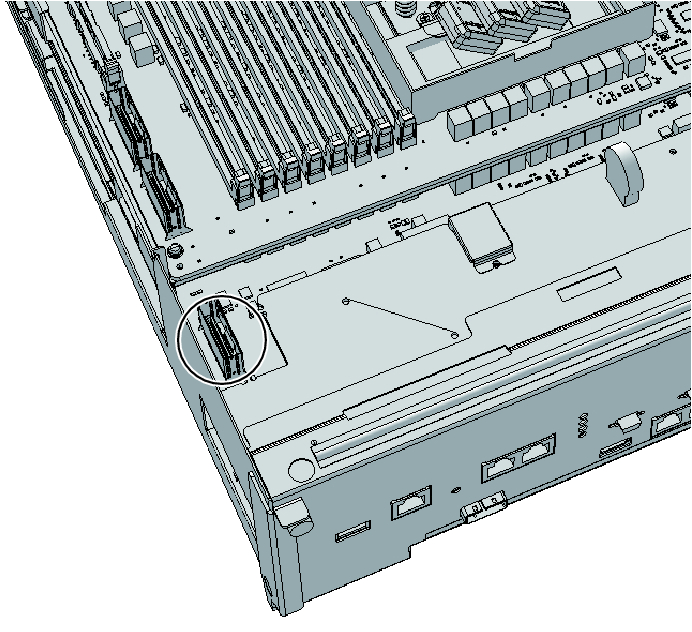
- Two PCIe cables (A in Figure 9-12) on the left side connect the CPU memory units upper and lower. Remove these cables from the CPU memory unit upper, and push the longer one at the front toward the outside of the chassis.
|
Figure 9-12 Removing the left-side cables
|
|
- Of the two PCIe cables on the left side, remove the rear one from the CPU memory unit lower too since it is short.
|
Figure 9-13 Removing the PCIe cable from the left side rear
|
|
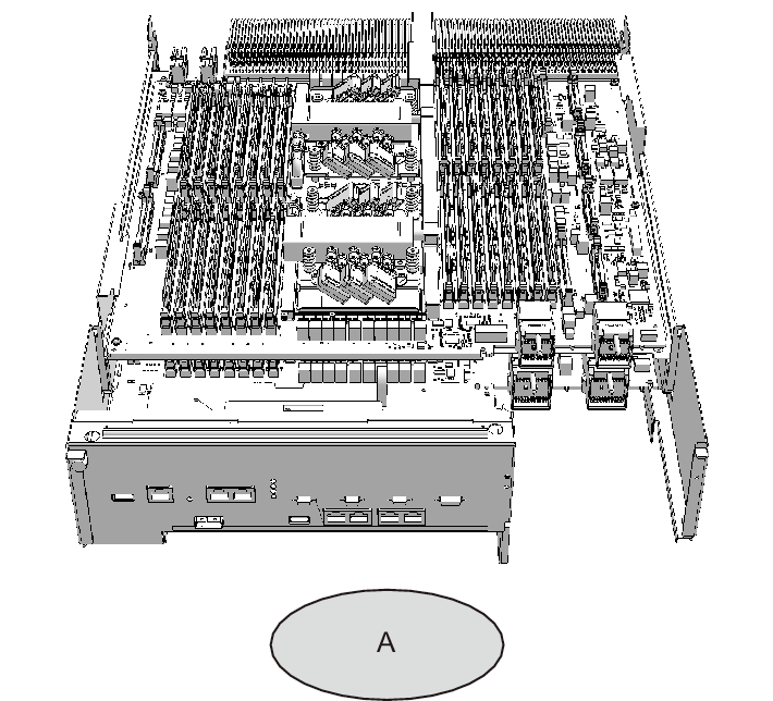
Perform the following work from the rear of the chassis. A in Figure 9-14 shows the standing position of a field engineer.
|
Figure 9-14 Standing position of a field engineer
|
|
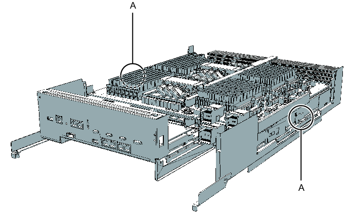
- Raise the levers (A in Figure 9-15) on the right and left sides to release the CPU memory unit upper.
|
Figure 9-15 Positions of right and left levers
|
|
- While holding the levers, lift the CPU memory unit upper slightly.
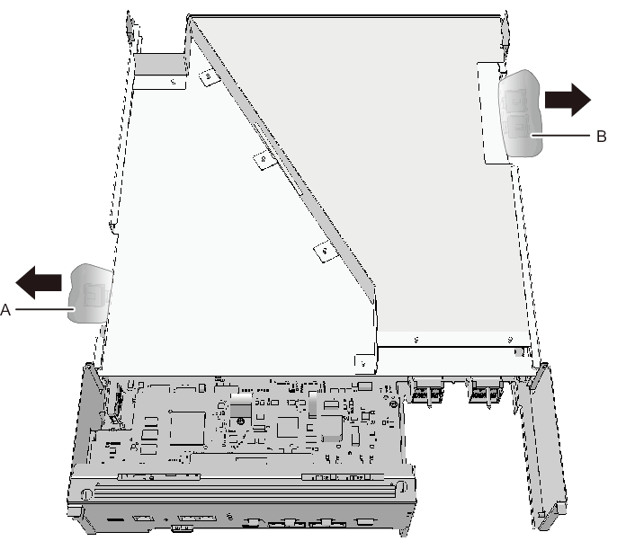
- If PCIe cables are connected to the CPU memory unit lower that has a filler unit mounted, push the PCIe cables (A and B in Figure 9-16) toward the outside of the chassis.
|
Figure 9-16 How to push PCIe cables toward the outside
|
|
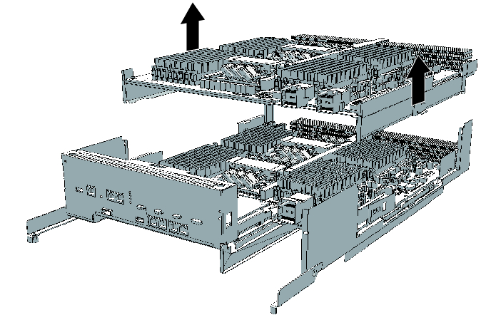
- With your hands at Handling Position on both sides of the CMUU, hold and lift the CPU memory unit upper or filler unit, and then remove it carefully.
| Note - Be careful when removing the CPU memory unit upper or the filler unit so that it does not catch on any PCIe cable. |
| Note - Place the removed CPU memory unit upper on a grounded antistatic ESD mat. |
|
Figure 9-17 Removing CPU memory unit upper
|
|
< Previous Page | Next Page >