9.10.1 Installing the CPU memory unit upper
9.10.1 Installing the CPU memory unit upper
| Note - A part of the procedure varies depending on the CPU memory unit type. To determine the CPU memory unit type, check the label in Figure 9-2. |
Install the CPU memory unit upper on the CPU memory unit lower. When replacing the CPU memory unit lower, install the CPU memory unit upper on the new CPU memory unit lower.
For expansion of a CPU memory unit upper, perform the same procedure. When removing the CPU memory unit upper, install a filler unit in its place.
For expansion of a CPU memory unit upper, perform the same procedure. When removing the CPU memory unit upper, install a filler unit in its place.
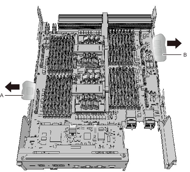
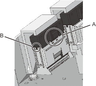
- When installing a filler unit for the CPU memory unit lower connected to PCIe cables, push the PCIe cables (A and B in Figure 9-61) toward the outside of the chassis.
| Note - Be careful when removing the filler unit so that it does not catch on any PCIe cable. |
| Note - Use PCIe cables without removing the packaging material covering the connector part of the cable. |
| Note - The shortest PCIe cable is no longer necessary during maintenance. Connect it to the removed CPU memory unit, and return them together. |
|
Figure 9-61 How to push PCIe cables toward the outside
|
|
- Install the CPU memory unit upper or filler unit on the CPU memory unit lower.
- - When installing the CPU memory unit upper
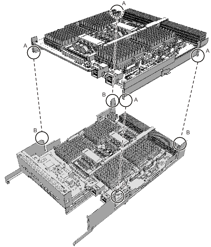
Carefully install the CPU memory unit upper by setting the four guides (A in Figure 9-62) of the CPU memory unit upper into the grooves (B in Figure 9-62) of the CPU memory unit lower.
| Note - Confirm that the levers on the left and right sides of the CPU memory unit upper are closed. |
|
Figure 9-62 Guide positions of the CPU memory unit upper
|
|
- - When installing a filler unit
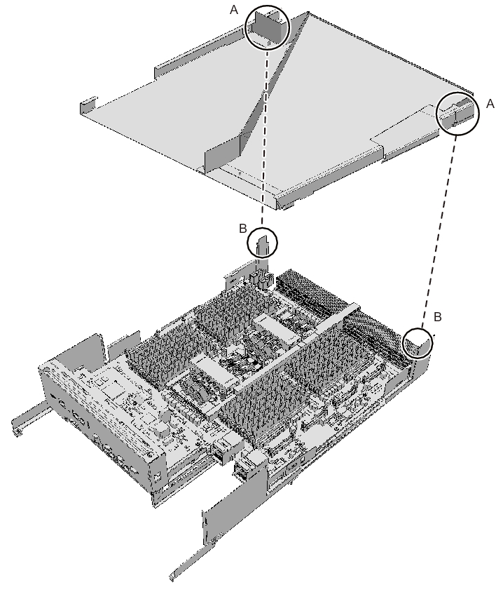
Install the filler unit by setting the two guides (A in Figure 9-63) of the filler unit into the grooves (B in Figure 9-63) of the CPU memory unit lower.
|
Figure 9-63 Filler unit guide locations
|
|
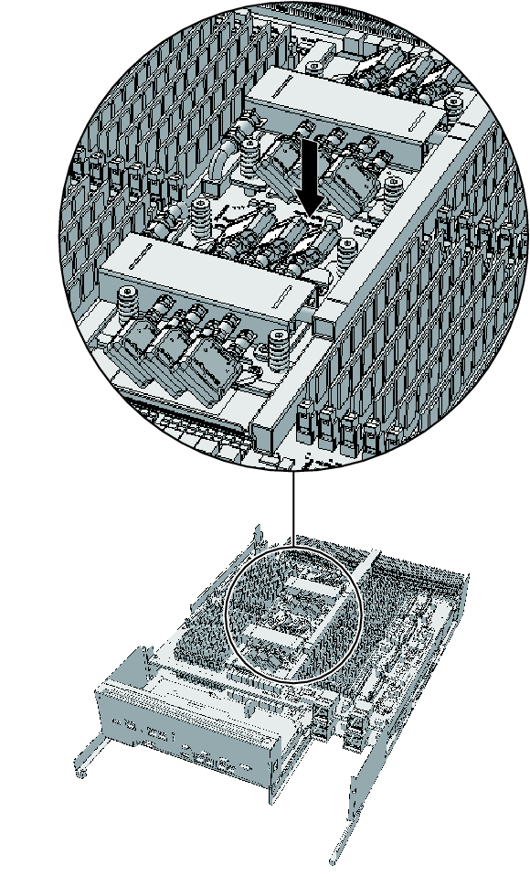
- Install the CPU memory unit upper by holding it down from the center where the label "PUSH" is applied and then pushing it into place.
|
Figure 9-64 Position where the CPU memory unit upper is pushed
|
|
- To connect the CPU memory units upper and lower, connect four PCIe cables (two each on the right and left sides) to the CPU memory unit upper.
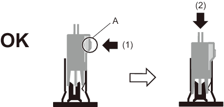
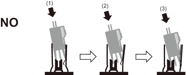
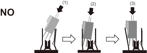
- Position the PCIe cable so that its locking bracket (A in Figure 9-65) is on the memory slot side of the CPU memory unit upper. While pressing the PCIe cable locking bracket ((1) in Figure 9-65), insert the cable straight down all the way ((2) in Figure 9-65).
- - Inserting the PCIe cable connector
|
Figure 9-65 Correctly inserted PCIe cable connector
|
|
|

|
Figure 9-66 Wrongly inserted PCIe cable connector (at an angle)
|
|
|
Figure 9-67 Wrongly inserted PCIe cable connector (flipped)
|
|
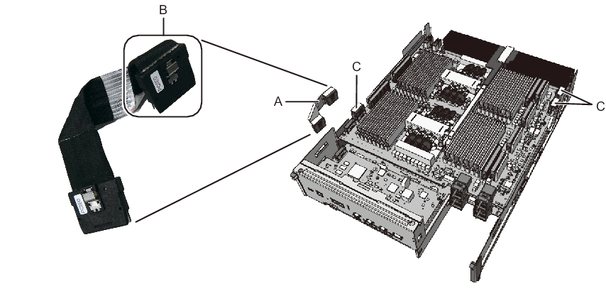
- - Connecting the PCIe cable
| Note - Of the four PCIe cables, three are already connected to the CPU memory unit lower (C in Figure 9-68). Just connect these three cables to the CPU memory unit upper. On the left side as viewed from the rear, also connect the nearest PCIe cable (short) (A in Figure 9-68) of the two PCIe cables on this side to the CPU memory unit lower. One end of this PCIe cable (short) has the connector that covers the folded cable (B in Figure 9-68, shown as PCIE0 on the label). Connect this end to the CPU memory unit upper, and the other end to the CPU memory unit lower. |
|
Figure 9-68 PCIe cable (short) connection
|
|
- Confirm that all the PCIe cables are firmly connected.
- - The PCIe cable locking bracket is facing the memory slots on the CPU memory unit upper.- The PCIe cable locking bracket (A in Figure 9-69) is secured.- After implementation, the PCIe cable connector is vertically connected.
(No depression or protrusion is visible on the side of the joined PCIe cable connector and CPU memory unit upper connector (B in Figure 9-69).)
|
Figure 9-69 Checking a PCIe cable connection
|
|
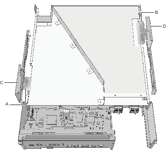
- If a filler unit for the CPU memory unit upper has been installed, hold the packaging material (A and B in Figure 9-70) of the PCIe cable connector part over the top of the left- and right-side guides (C and D in Figure 9-70).
|
Figure 9-70 Packaging material of the PCIe cable connector part
|
|
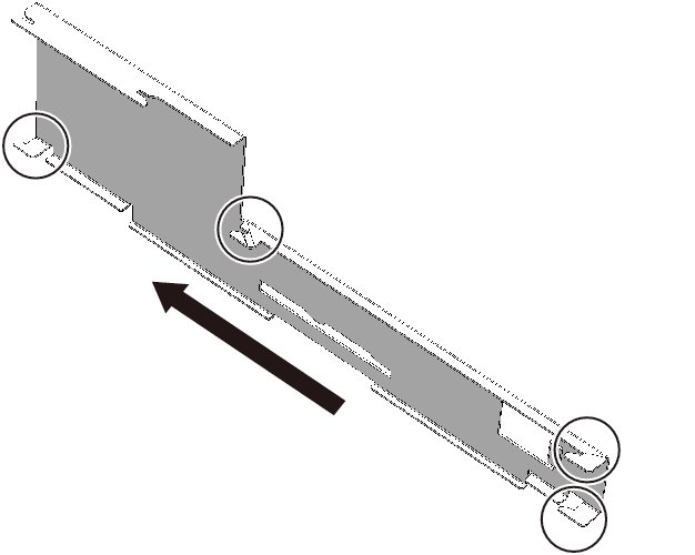
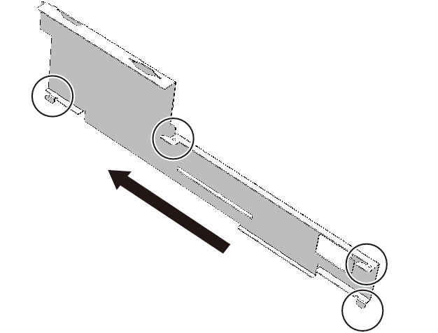
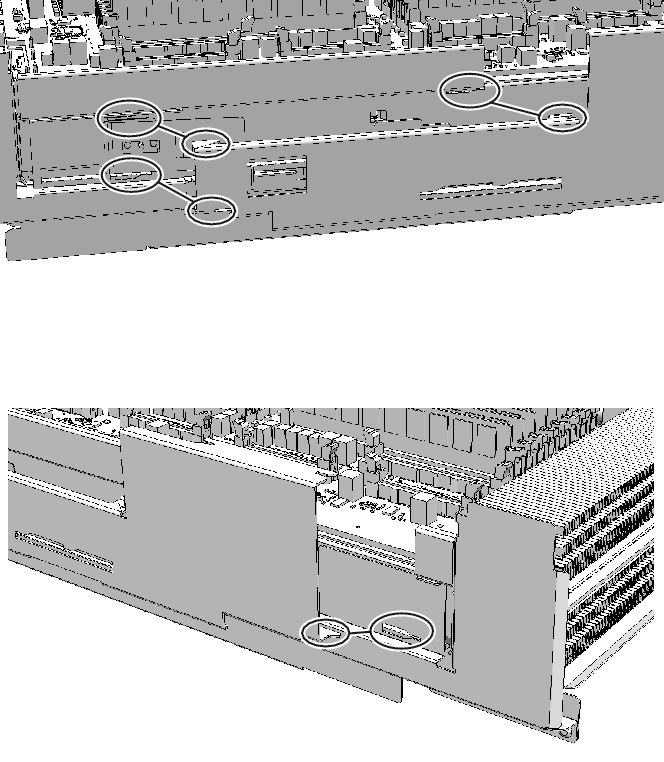
- Align the four clips on each of the left- and right-side guides to the grooves in the frame of the CPU memory unit lower to install them. Slide in the guides to lock them.
| Note - When replacing the CPU memory unit lower, use the left- and right-side guides supplied with the new CPU memory unit lower. |
| Note - Be careful not to damage any PCIe cable when installing the left- and right-side guides. Also be careful not to pinch the packaging material of the PCIe cable connector part with any clip on the left- and right-side guides. |
|
Figure 9-71 Locations of the clips on the left- and right-side guides (for the SPARC M10-4/M10-4S with a FRAME-A CPU memory unit)
|
|
|
Figure 9-72 Locations of the clips on the left- and right-side guides (for the SPARC M10-4/M10-4S with a FRAME-B CPU memory unit)
|
|
|
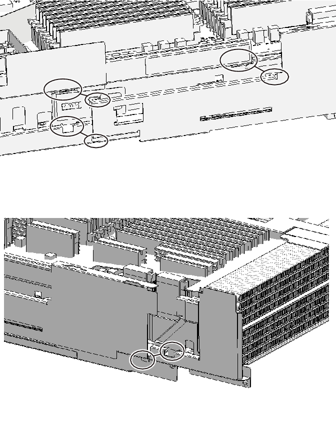
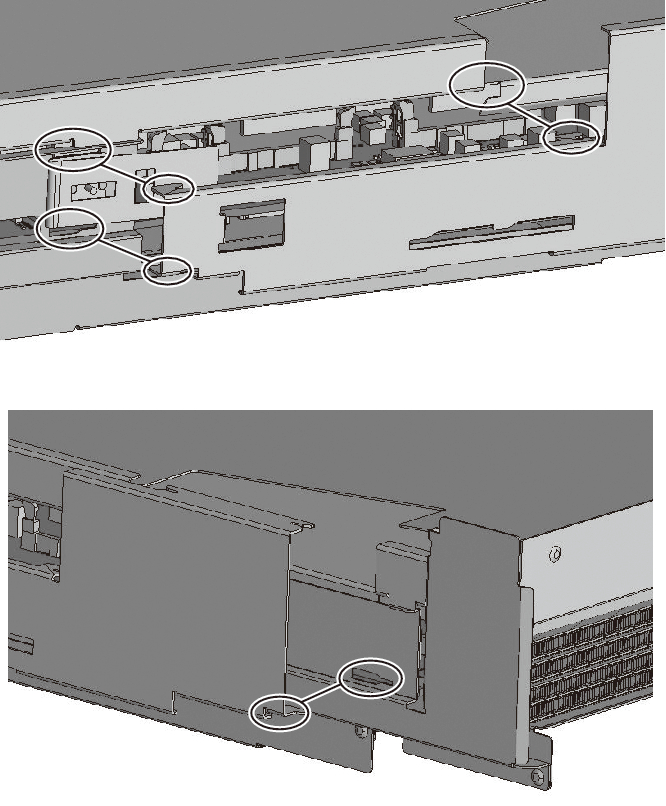
Figure 9-73 CPU memory unit upper and locations of the clips on the side guide (for the SPARC M10-4/M10-4S with a FRAME-A CPU memory unit)
|
|
|
Figure 9-74 CPU memory unit upper and locations of the clips on the side guide (for the SPARC M10-4/M10-4S with a FRAME-B CPU memory unit)
|
|
|
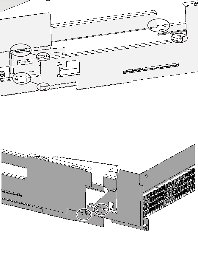
Figure 9-75 Filler unit of the CPU memory unit upper and locations of the clips on the side guide (for the SPARC M10-4/M10-4S with a FRAME-A CPU memory unit)
|
|
|
Figure 9-76 Filler unit of the CPU memory unit upper and locations of the clips on the side guide (for the SPARC M10-4/M10-4S with a FRAME-B CPU memory unit)
|
|
- Unlock (push) the top cover of the CPU memory unit, and install the cover by sliding it.
| Note - When replacing the CPU memory unit lower, use the top cover supplied with the new CPU memory unit lower. |
< Previous Page | Next Page >