5.3 Connecting Cables to the Crossbar Box
5.3 Connecting Cables to the Crossbar Box
This section describes the procedure for connecting the serial cable to the crossbar box.
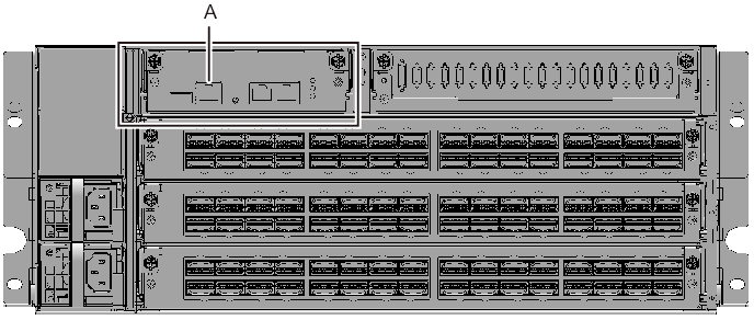
- Connect the serial cable supplied with the chassis from the serial port of the XSCF unit (A in Figure 5-18) to the system management terminal.
In a building block configuration, the batch operation is performed in the chassis of the master XSCF. Connect the serial cable to the master XSCF.
| Note - In a building block configuration with connections through crossbar boxes, XBBOX#80 is usually the master XSCF, and XBBOX#81 is the standby XSCF. If the master is switched, XBBOX#81 becomes the master XSCF, and XBBOX#80 becomes the standby XSCF. |
| Note - In a building block configuration connected via crossbar box, no serial cables are connected to the SPARC M12-2S. |
|
Figure 5-18 Serial Port Location on a Crossbar Box
|
|
- Confirm that the power cords of the SPARC M12-2S and crossbar box are connected to the PDU of the expansion rack.
The power cords of the SPARC M12-2S and crossbar box are shipped connected to the PDU of the expansion rack.
When the SPARC M12-2S has been mounted at the installation site, connect the power cords to the PDU at this point. - Confirm that the CB switch attached to the PDU of the expansion rack is off.
When pulled out, the CB switch is turned off. When pushed in, the switch is turned on.
For the locations of the CB switches on the PDUs, see A in Figure 3-3 in "3.3.1 Connecting the Power Cords to the Power Distribution Units of an Expansion Rack."
< Previous Page | Next Page >