18.4.1 Installing a Cable Between the Crossbar Backplane Unit and Terminal Board
18.4.1 Installing a Cable Between the Crossbar Backplane Unit and Terminal Board
Install the cable (SIG) or cable (PWR) connecting the crossbar backplane unit and terminal board.
- Connect the cable to the connector of the crossbar backplane unit.
Install a cable that has the same shape as that of the removed cable.
|
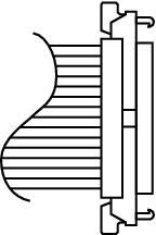
Figure 18-24 Connector Shape (Cable (SIG))
|
|
- Secure the cable with a clamp.
- Support the fan shelf from below with one hand, and carefully insert it into the chassis.
Arranging the cables in the center makes it easier to install the fan shelf. - Tighten the three screws securing the fan shelf.
- Connect the two cables to the fan shelf.
- Install the lower cover, and secure it with one screw.
- Install the upper cover.
- Slide the right and left stoppers of the upper cover outward, and secure the cover with two screws.
- Install all the fan units.
For details, see "15.4 Installing a Fan Unit." - Install the front cover.
For details, see "6.1.2 Installing the Front Cover."
< Previous Page | Next Page >